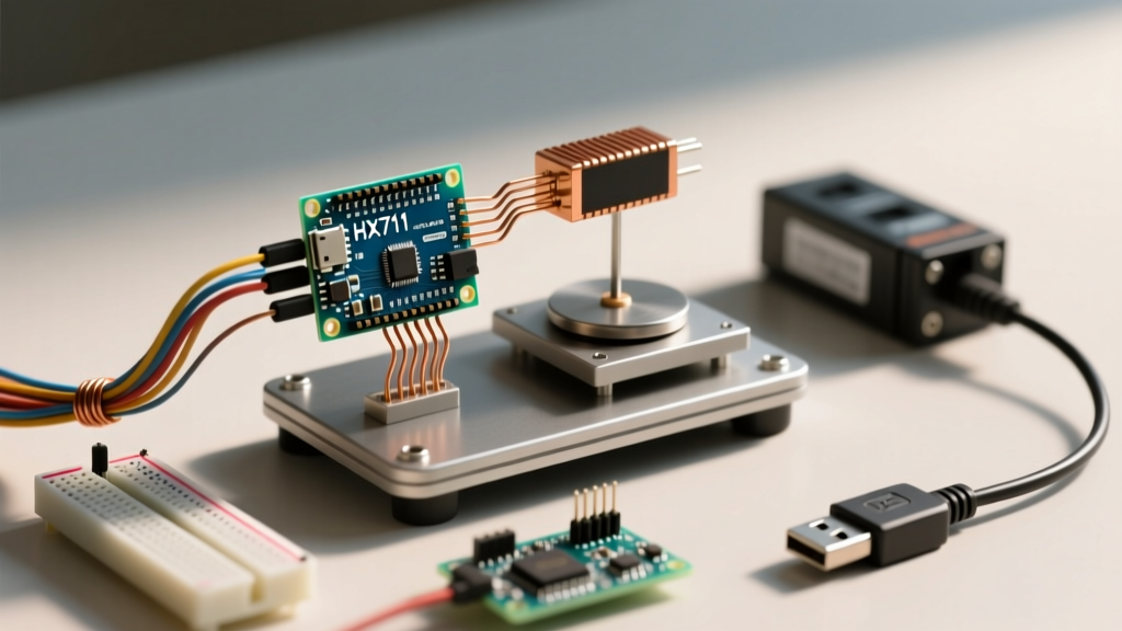

If you are building a digital scale, the direct answer to your hardware question is this: use a strain gauge load cell paired with an HX711 24-bit analog-to-digital converter (ADC) breakout board. The Arduino cannot read the microvolt-level changes from a load cell directly; the HX711 amplifies and digitizes the signal into a clean serial stream. However, 90% of scale builds fail not because of the code, but due to mechanical mounting errors, swapped Wheatstone bridge wires, or blocking library functions that freeze the microcontroller.
This guide provides a decision-forward framework to select your hardware, a non-blocking code architecture to prevent MCU lockups, and a targeted debugging matrix for when your serial monitor spits out garbage data.
The Quick Decision: Which Load Cell and Amplifier to Buy?
Load cells come in various geometries and capacities. Picking the wrong physical shape for your mounting setup will result in zero flex at the strain gauge, meaning zero change in resistance and a scale that reads exactly 0.00 regardless of weight.
| If your application is... | Required Capacity | Best Sensor Geometry | Amplifier Choice |
|---|---|---|---|
| Small bench scale / postal scale | 1kg - 5kg | Straight-bar (single point) | HX711 (Standard) |
| Luggage scale / body scale | 10kg - 50kg | Straight-bar or Half-bridge | HX711 (Standard) |
| Industrial hopper / pallet scale | 100kg - 500kg+ | S-Type (tension/compression) | HX711 (Shielded) or INA125P |
Parts List and Pin Mapping for the Arduino Uno R3
Estimated Time: 90 minutes
Target Board: Arduino Uno R3 (ATmega328P DIP or SMD variant)
Required Hardware
- Microcontroller: Arduino Uno R3 (or Nano v3 with identical ATmega328P pinout)
- Amplifier: HX711 Breakout Board (Green PCB variant preferred; red variants sometimes lack the `RATE` pin pull-down resistor, locking you to 10 SPS instead of 80 SPS)
- Sensor: 20kg CZL601 Straight-bar Load Cell (includes 4-wire cable)
- Mounting: 2x M4 or M5 bolts, washers, and a rigid base plate (wood or aluminum)
- Wiring: Dupont jumper wires (female-to-female and male-to-female)
Pin Mapping and Wiring Table
The load cell uses a Wheatstone bridge circuit. It requires excitation voltage (E) and outputs a differential signal (A). Getting these backward won't fry the sensor, but it will result in reversed or zero readings.
| Component | Wire / Pin | Connects To | Function |
|---|---|---|---|
| Load Cell | Red (E+) | HX711 E+ | Excitation Voltage (+) |
| Load Cell | Black (E-) | HX711 E- | Excitation Voltage (-) |
| Load Cell | White (A+) | HX711 A+ | Signal Output (+) |
| Load Cell | Green (A-) | HX711 A- | Signal Output (-) |
| HX711 | VCC | Arduino 5V | Power (See note below) |
| HX711 | GND | Arduino GND | Common Ground |
| HX711 | DT (Data) | Arduino Pin D2 | Serial Data Out |
| HX711 | SCK (Clock) | Arduino Pin D3 | Serial Clock In |
Step-by-Step Wiring and Mechanical Calibration
A load cell measures physical deformation (strain). If the metal bar cannot bend, the strain gauge inside cannot change resistance, and your scale will not work.
- Create a Cantilever or Bridge Mount: Do not lay the load cell flat on a table. Bolt one end of the 20kg bar firmly to a heavy base. Leave the other end completely suspended in the air. The weight must be applied to the suspended end to create a bending moment across the center hole where the strain gauge lives.
- Wire the Load Cell to the HX711: Strip the 4 load cell wires and screw them into the HX711's left-side terminal block (E+, E-, A+, A-). Ensure no stray copper strands are bridging the terminals.
- Wire the HX711 to the Arduino: Connect DT to D2, SCK to D3, VCC to 5V (or 3.3V), and GND to GND.
- Determine the Calibration Factor: The raw output of the HX711 is a 24-bit integer (ranging from -8,388,608 to 8,388,607). You must map this to grams or kilograms. Place a known weight (e.g., a 1kg dumbbell or a calibrated bag of sugar) on the scale. Divide the raw reading change by the known weight to get your calibration factor. (e.g., If 1000g causes a raw change of 42,000, your factor is 42.0).
Complete Arduino Code with HX711 Error Handling
Most tutorials use the original `HX711` library by Bogde. That library uses blocking `delayMicroseconds()` calls while waiting for the HX711 to signal data readiness. If the HX711 disconnects or the wire breaks, the Arduino freezes permanently until you press the reset button.
Instead, we use the non-blocking HX711_ADC library by Olav Kallhovd. It checks the pin state without halting the CPU, allowing you to run displays, buttons, and WiFi tasks simultaneously.
#include

// --- PIN DEFINITIONS ---
const int HX711_DOUT = 2; // DT pin
const int HX711_SCK = 3;  // SCK pin

// --- CALIBRATION ---
// Change this value based on your Step 4 calibration math
const float CALIBRATION_FACTOR = 42.0;

HX711_ADC LoadCell(HX711_DOUT, HX711_SCK);

unsigned long lastPrintTime = 0;
const int printInterval = 500; // Print every 500ms

void setup() {
  Serial.begin(9600);
  Serial.println(F("Initializing HX711..."));

  // Initialize the library, set gain to 128 (Channel A)
  LoadCell.begin();

  // Start taring (zeroing) the scale.
  // The 'true' parameter enables non-blocking mode for the tare process.
  LoadCell.start(2000, true);

  if (LoadCell.getTareTimeoutFlag()) {
    Serial.println(F("ERROR: HX711 Tare Timeout! Check wiring."));
    while(1); // Halt execution safely
  }

  LoadCell.setCalFactor(CALIBRATION_FACTOR);
  Serial.println(F("Scale Ready. Place weight on sensor."));
}

void loop() {
  // Update() checks if new data is available without blocking the MCU
  // It returns true if a new reading was successfully processed
  boolean newDataReady = LoadCell.update();

  if (newDataReady) {
    unsigned long currentTime = millis();
    if (currentTime - lastPrintTime >= printInterval) {
      lastPrintTime = currentTime;

      float weight = LoadCell.getData();

      // Error handling for disconnected sensor or over-range
      if (LoadCell.getSignalTimeoutFlag()) {
        Serial.println(F("ERROR: HX711 signal timeout. Check DT/SCK wires."));
        LoadCell.clearSignalTimeoutFlag();
      } else {
        Serial.print(F("Weight: "));
        Serial.print(weight, 1);
        Serial.println(F(" g"));
      }
    }
  }

  // You can add button reads, LCD updates, or WiFi tasks here
  // without interrupting the scale's data polling.
}
Debugging: First 3 Things to Check When Readings Fail
When your serial monitor misbehaves, do not rewrite your code. The issue is almost always electrical or mechanical. Here is the ranked decision path for the most common failure modes.
1. Symptom: Serial Monitor prints "ERROR: HX711 Tare Timeout!" or readings are stuck at exactly 0.00
Root Cause: The Arduino is not receiving the clock/data handshake from the HX711. The HX711 requires the SCK line to be LOW to operate. If SCK is held HIGH for more than 60 microseconds, the chip enters power-down mode.
- Fix A: Verify you have not swapped DT and SCK pins. DT must be on D2, SCK on D3.
- Fix B: Check that the HX711 VCC is receiving adequate voltage. Measure between VCC and GND on the breakout board with a multimeter; it must read >2.7V.
- Fix C: If using a breadboard, ensure the HX711 header pins are fully seated. Breadboard contact resistance on the SCK line can cause voltage drops that mimic a HIGH state.
2. Symptom: Readings are wildly fluctuating (e.g., jumping between -500g and +800g) or drifting continuously upward
Root Cause: Analog noise, missing ground reference, or thermal drift.
- Fix A: Switch the HX711 VCC from the Arduino 5V pin to the 3.3V pin to eliminate LDO thermal drift.
- Fix B: Ensure the Arduino GND and HX711 GND share a direct, short connection. Do not daisy-chain grounds through a long breadboard power rail.
- Fix C: Keep the 4-wire load cell cable away from AC mains wiring or high-current DC motor lines to prevent electromagnetic interference (EMI) from inducing microvolts in the unshielded signal wires.
3. Symptom: Readings go negative when weight is added, or the raw value maxes out at 8388607
Root Cause: Polarity inversion or over-range saturation.
- Fix A (Negative values): Swap the White (A+) and Green (A-) wires on the HX711 terminal block. This simply reverses the differential signal polarity.
- Fix B (8388607 max out): The HX711 outputs its maximum 24-bit positive integer (0x7FFFFF) when the input voltage exceeds the programmable gain amplifier's range. Your calibration factor is likely wrong, or the load cell is bottoming out mechanically against the mounting plate. Increase the physical gap under the suspended end of the load cell.
Extending or Simplifying Your Scale Build
Once your base scale is reading reliably to the gram, you will likely want to integrate it into a larger system. Here is how to scale the project up or down based on your end goal.
To Simplify (Standalone IoT Scale)
Ditch the Arduino Uno and the jumper wires. Use an ESP32 DevKit V1 combined with a dedicated HX711 PCB that solders directly to the ESP32 headers. The ESP32 allows you to push the weight data via MQTT over WiFi to Home Assistant or a cloud dashboard. The code above is 100% compatible with the ESP32; simply change the pin definitions to GPIO pins that do not conflict with the ESP32's internal flash SPI (avoid GPIO 6-11, and use GPIO 4 for DT and GPIO 5 for SCK).
To Extend (High-Capacity 4-Point Platform Scale)
If you need to build a bathroom scale or a pallet scale, a single 20kg bar is insufficient. You must use four half-bridge load cells (often sold as "body scale sensors"). The Wiring Hack: You do not need four HX711 boards. You can wire the four half-bridge sensors together to form one giant, full Wheatstone bridge. Wire the Excitation (E) and Signal (A) lines in a specific series-parallel loop so that the bending of any of the four sensors unbalances the bridge, feeding a single, summed analog signal into one HX711 board. Refer to the SparkFun HX711 Hookup Guide for the exact 4-cell schematic.
By prioritizing mechanical mounting, using non-blocking code, and understanding the Wheatstone bridge polarity, your load sensor Arduino project will transition from a frustrating breadboard experiment to a reliable, precision measurement tool.