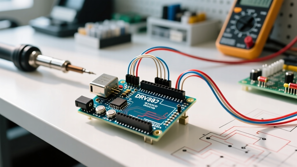
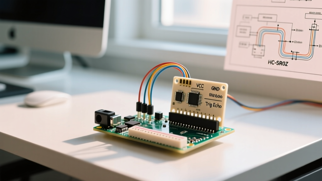
For raw TO-92 hall effect sensors like the A3144 (digital switch) or SS49E (analog linear), hold the flat stamped side facing you with the pins pointing down. From left to right, the pins are VCC (Pin 1), GND (Pin 2), and OUT (Pin 3). For 4-pin breakout modules like the KY-024, the silkscreen typically reads GND, VCC, DOUT (Digital), and AOUT (Analog). If you are wiring industrial pre-pigtailed sensors, IEC 60446 standardizes the colors to Brown (+V), Blue (0V), and Black (Signal).
Master Hall Effect Sensor Pinout & Wire Color Table
The table below covers the most common raw ICs, hobbyist breakout boards, and industrial pigtail standards. Use this as your bench reference before applying power.
| Sensor Type / Form Factor | Pin 1 / Wire 1 | Pin 2 / Wire 2 | Pin 3 / Wire 3 | Pin 4 / Wire 4 | Orientation / Standard |
|---|---|---|---|---|---|
| Raw TO-92 IC (A3144, SS49E, DRV5055) | VCC (+) | GND (-) | OUT (Signal) | N/A | Flat side facing viewer, pins down |
| Raw SIP-3 IC (US5881, HAL248) | VCC (+) | GND (-) | OUT (Signal) | N/A | Label side facing viewer, pins down |
| 3-Pin Digital Module (KY-003) | GND | VCC (+5V) | DOUT (Digital) | N/A | Silkscreen varies; verify with meter |
| 4-Pin Analog/Digital Module (KY-024) | GND | VCC (+5V) | DOUT (Digital) | AOUT (Analog) | Silkscreen usually reliable; DOUT needs trimpot |
| Industrial M12 Pigtail (IEC 60446) | Brown (+VDC) | White (N/C or N/O) | Blue (0V / GND) | Black (Signal Out) | Global standard for 3/4-wire DC proximity sensors |
| Legacy US Industrial Pigtail | Black (Hot/+V) | White (Neutral/Return) | Red (Signal Out) | N/A | Older US manufacturing convention (pre-IEC harmonization) |
Standard Pinouts and Module Variants in Practice
Understanding what each row in the table above means for your microcontroller is critical, especially when mixing 5V sensors with 3.3V logic boards like the ESP32 or Raspberry Pi Pico.
Raw ICs: Open-Drain vs. Push-Pull
The Texas Instruments hall effect portfolio and legacy Allegro parts like the A3144 use an open-drain output on Pin 3. This means the IC can pull the signal line to ground, but it cannot drive it high. You must provide an external pull-up resistor (typically 4.7kΩ to 10kΩ) between the OUT pin and your microcontroller's VCC.
The ESP32 Level-Shifting Trick: The A3144 requires a minimum of 4.5V on VCC to operate, but the ESP32 GPIO pins will fry if fed 5V. Because the A3144 is open-drain, you can power the sensor's VCC pin with 5V, but pull the OUT pin up to the ESP32's 3.3V rail using a 10kΩ resistor. The sensor will safely pull the 3.3V line to ground without ever exposing the ESP32 to 5V.
Breakout Modules: The Trimpot Dependency
Modules like the KY-024 include an onboard LM393 comparator. The AOUT pin provides a raw ratiometric voltage (0V to VCC) that you must read with an ADC pin. The DOUT pin, however, will not change state until the magnetic field crosses the threshold set by the blue trimpot on the board. If your DOUT pin is stuck HIGH or LOW, adjust the trimpot with a small Phillips screwdriver while holding a magnet near the sensor.
Regional Wire Color Standards for Industrial Sensors
When you move from hobbyist breakout boards to industrial hall effect proximity sensors (often terminated with M8 or M12 circular connectors), wire colors are governed by regional electrical standards. Miswiring these will instantly short your 24V PLC supply or fry the sensor's internal transistor.
Industrial hall sensors typically operate on 10-30V DC. Never connect a 24V industrial sensor directly to an Arduino or ESP32 GPIO. Use an optocoupler or a resistor voltage divider to step the 24V signal down to 3.3V/5V logic levels.
Which Standard Applies to Your Region?
- IEC 60446 (Europe, Asia, Modern Global Standard): This is the dominant standard for DC sensor wiring today. Brown is positive (+V), Blue is negative (0V/GND), and Black is the primary signal output. If a fourth wire is present for a complementary output (N/C vs N/O), it is typically White.
- Old UK (Pre-2004 Harmonization): Older British machinery often used Red for positive, Black for negative, and Green (or Yellow) for the signal. If you are retrofitting a legacy UK machine, verify the wires with a multimeter; assuming IEC colors on a pre-2004 UK loom will cause a dead short.
- US NEC / Legacy American: While the NFPA 70 (NEC) primarily governs AC power and building wiring, legacy US DC sensor manufacturers often borrowed AC conventions: Black for Hot (+V), White for Neutral/Return (GND), and Red for Signal. Always check the specific manufacturer's datasheet (e.g., Honeywell, Banner Engineering) when dealing with unmarked US industrial pigtails.
The "Rows People Get Wrong" Troubleshooting Guide
Even with the table in front of you, these specific pinout and wiring mistakes account for 90% of the hall effect sensor issues I see on the workbench.
- Confusing the TO-92 Flat and Rounded Sides: The pinout (VCC, GND, OUT) only applies when the flat, stamped side is facing you. If you look at the rounded side, the pin order is exactly reversed (OUT, GND, VCC). Swapping VCC and OUT will instantly destroy the internal silicon and cause the IC to overheat.
- Assuming DOUT Works Out-of-the-Box: On 4-pin modules, the digital output (DOUT) is factory-set to a random magnetic threshold. Beginners often wire it up, wave a weak fridge magnet over it, and assume the sensor is broken. You must adjust the onboard potentiometer to tune the trip point to your specific magnet's Gauss rating.
- Ignoring the Pull-Up Resistor on Raw ICs: If you wire an A3144 directly to an ESP32 pin without a pull-up resistor, the GPIO will float. You will read random 1s and 0s in the serial monitor, or the pin will trigger interrupt routines phantom-style. Always use a 4.7kΩ to 10kΩ pull-up.
- Misinterpreting Analog Polarity: Linear sensors like the SS49E output a quiescent voltage of VCC/2 (e.g., 2.5V on a 5V supply) when no magnet is present. A South pole drives the voltage up toward VCC; a North pole drives it down toward 0V. If your code expects 0V at rest, your logic will fail.
Safe Interpretation When Markings Are Faded or Missing
When you pull a salvaged hall sensor from a scrapped BLDC motor or a faded industrial limit switch, the silkscreen or stamped text is often illegible. Do not guess the pinout by applying 5V blindly. Use this bench procedure to safely map the pins.
Step 1: Identify VCC and GND via Diode/Continuity Test
Set your multimeter to diode test mode. Probe the pins in pairs. Hall ICs have internal reverse-polarity protection diodes and voltage regulators. You will typically read a forward voltage drop (around 0.5V to 0.7V) between the VCC and GND pins in one direction, and an open loop (OL) in the reverse. The pin that acts as the anode (positive lead of your meter) in the forward-biased reading is usually GND, but verify this against the specific IC's datasheet if possible. If the IC has a metal can (like some SIP packages), the can is almost always tied to GND.
Step 2: Use a Current-Limited Power Supply
Set a bench power supply to 5.0V with a strict current limit of 30mA. Apply power to your suspected VCC and GND pins. If the current spikes and the supply trips, you have the pins reversed or the IC is shorted. If it draws a quiescent 2mA to 5mA, you have found the correct power pins.
Step 3: Trace the Output with a Neodymium Magnet
With the IC powered, connect your multimeter (set to DC Voltage) between the suspected OUT pin and GND. For a digital switch, you should read either VCC (pulled high) or ~0V. Bring a strong neodymium magnet close to the sensor's branded face. If the voltage snaps to the opposite rail, you have successfully identified the output pin. For linear (analog) sensors, you will see the voltage smoothly drift from the VCC/2 quiescent point as the magnet approaches and recedes.
If you are trying to desolder a 3-pin hall sensor from a tight BLDC stator without melting the plastic housing, use a low-melt solder (like Chip Quik) mixed with standard 63/37 rosin core. The lowered melting point lets you pull the IC off with tweezers before the heat transfers to the sensor's epoxy body, preserving the internal die for reuse.