
Decoding the ESP32 Temperature Sensor Ecosystem
Integrating an esp32 temperature sensor into your IoT or industrial project requires more than just wiring a few pins. The ESP32’s dual-core architecture, WiFi/Bluetooth RF interference, and specific I2C/1-Wire peripheral quirks mean that generic Arduino libraries often fail under heavy processing loads. Whether you are relying on the chip's internal thermal monitor, deploying a rugged DS18B20 for outdoor weather stations, or wiring a high-precision TMP117 for laboratory equipment, selecting the correct driver is critical for system stability.
This guide bypasses the basic tutorials and dives deep into the library architecture, memory footprints, and hardware-level driver configurations required to extract reliable thermal data from the ESP32 ecosystem in 2026 and beyond.
Internal vs. External: Which Driver Do You Actually Need?
The Hidden Internal ESP32 Sensor
Many developers overlook the fact that the ESP32 die contains an internal temperature sensor. Historically, this was only accessible via the ESP-IDF (IoT Development Framework) using the driver/temp_sensor.h peripheral API. However, modern iterations of the Arduino-ESP32 core now expose this via the temperatureRead() function.
Expert Caveat: The internal sensor is designed to monitor the silicon die temperature, not the ambient room temperature. Due to heat generated by the CPU and RF transceivers, internal readings typically sit 5°C to 12°C higher than ambient. If you must use it for ambient estimation, you need to implement a software calibration offset in your driver logic, and ensure the WiFi radio is duty-cycled to prevent thermal skewing during ADC sampling.
External Precision Sensors
For true ambient or environmental monitoring, external sensors are mandatory. The choice of sensor dictates the bus protocol, which in turn dictates the driver library you must use. The most common architectures are 1-Wire (DS18B20), I2C/SPI (BME280/BMP280), and high-resolution I2C (TMP117).
Library Showdown: RAM, Flash, and Execution Speed
Choosing the right library impacts your ESP32's free heap memory, which is crucial when running TLS-encrypted MQTT connections alongside sensor polling. Below is a comparative analysis of the most reliable driver libraries available for the ESP32.
| Sensor Model | Protocol | Recommended Arduino Library | ESP-IDF Component | Approx. RAM Overhead | Best Use Case |
|---|---|---|---|---|---|
| Internal | Internal ADC | Native Core (temperatureRead) |
driver/temp_sensor |
< 1 KB | Chip thermal throttling |
| DS18B20 | 1-Wire | OneWireNg + DallasTemperature |
onewire_ng component |
~3.5 KB | Waterproof outdoor/liquid |
| BME280 | I2C / SPI | Adafruit_BME280 |
Bosch Official BME280 API | ~4.2 KB | Indoor HVAC / Weather |
| TMP117 | I2C | SparkFun_TMP117 |
Custom I2C wrapper | ~2.8 KB | Medical / Lab precision |
Deep Dive: 1-Wire DS18B20 Driver Configuration
The DS18B20 remains the most popular waterproof esp32 temperature sensor, but the 1-Wire protocol is notoriously hostile to the ESP32's dual-core RTOS environment. Traditional Arduino libraries like OneWire rely on software bit-banging with microsecond delays. On an ESP32, if a WiFi interrupt or a task switch occurs on the second core during a 1-Wire timing window, the bus timing collapses, resulting in CRC errors or the infamous '85°C' default power-on read.
The RMT Peripheral Solution
To solve this, advanced developers abandon the legacy OneWire library in favor of OneWireNg. This library leverages the ESP32’s RMT (Remote Control) peripheral. The RMT handles the microsecond pulse generation and reception entirely in hardware, completely immune to RTOS context switching and WiFi interrupts.
Hardware Wiring Rule: While standard 1-Wire guides recommend a 4.7kΩ pull-up resistor, the ESP32 operates at 3.3V logic. A 4.7kΩ resistor often results in rise-times that are too slow for the ESP32's stricter timing tolerances, especially on cable runs over 3 meters. Always use a 2.2kΩ or 3.3kΩ pull-up resistor to VCC (3.3V) when interfacing 1-Wire sensors with an ESP32.
I2C Clock Stretching and BME280 Driver Pitfalls
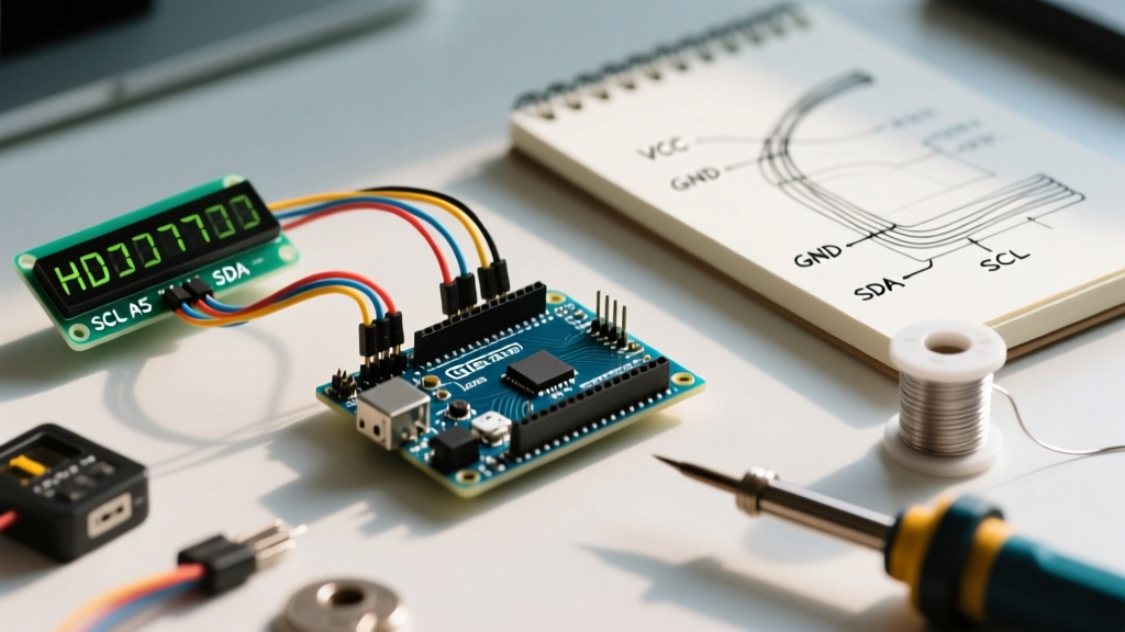
When integrating I2C-based sensors like the BME280 (which measures temperature, humidity, and pressure), developers frequently encounter bus lockups. This is often traced back to a known hardware quirk in early ESP32 silicon revisions regarding I2C clock stretching.
Clock stretching occurs when a peripheral (the sensor) holds the SCL line low to buy time for internal ADC conversions. Early ESP32 revisions (Rev 0 and Rev 1) had an APB clock timeout bug that would cause the I2C hardware state machine to hang indefinitely if the stretch exceeded a specific threshold. While the BME280 doesn't stretch the clock aggressively, other high-precision sensors do.
Driver Mitigation Strategies
- Update Silicon: Ensure you are using ESP32 Rev 3 or later (e.g., ESP32-WROOM-32E), which features hardware fixes for I2C clock stretching.
- Software I2C Fallback: If you are locked into older hardware, use a software I2C library (like
SoftwareWire) which bit-bangs the protocol and ignores the faulty hardware peripheral. - Bus Speed Reduction: In your Arduino setup, explicitly define
Wire.setClock(100000);. Pushing the I2C bus to 400kHz (Fast Mode) on long wires with high capacitance often causes NACK errors during the sensor's internal temperature conversion phase.
Real-World Troubleshooting Matrix
When your esp32 temperature sensor integration fails, the serial monitor usually provides cryptic clues. Use this diagnostic matrix to pinpoint driver and hardware faults:
Pro-Tip: Always implement a non-blocking timeout in your sensor polling loop. A hung I2C bus or a disconnected 1-Wire sensor should never be allowed to block the ESP32's main
loop()and starve the WiFi watchdog timer.
- Symptom: DS18B20 constantly reads
85.0°C.
Diagnosis: Parasitic power mode failure. The sensor lacks sufficient current to perform the temperature conversion. Fix: Wire the VDD pin to 3.3V instead of relying on parasitic power, or increase the pull-up resistor current. - Symptom: BME280 returns
-127.0°CorNaN.
Diagnosis: I2C NACK. The ESP32 cannot see the sensor at address0x76or0x77. Fix: Run an I2C scanner sketch. Check for missing pull-up resistors on SDA/SCL lines, or verify if the SDO pin is floating (it must be tied to GND or VCC to set the address). - Symptom: Internal sensor reads wildly fluctuating values (+/- 15°C).
Diagnosis: RF transmission thermal noise. Fix: Implement a rolling average filter (e.g., exponential moving average) in your code, and only sample the internal ADC immediately after the ESP32 wakes from deep sleep, before the WiFi radio powers up.
Authoritative References
To further explore the underlying C/C++ driver implementations and hardware registers, consult the official documentation:
- Espressif ESP-IDF Temperature Sensor API Reference - Detailed breakdown of the internal DAC calibration and hardware registers.
- Arduino Core for ESP32 GitHub Repository - Source code for the
temperatureRead()wrapper and Wire library I2C implementations. - Adafruit BME280 Breakout Wiring & Test Guide - Excellent primer on I2C addressing and basic library instantiation.