When planning practical ESP 32 projects for home automation or remote monitoring, power consumption and network reliability are the two biggest hurdles. A sensor node that drains a 18650 battery in three days or drops offline when the router reboots is useless. This guide walks through building a robust, deep-sleep environmental sensor using the ESP32-S3 and a Bosch BME280, publishing temperature, humidity, and pressure data to an MQTT broker.
This build targets the ESP32-S3-DevKitC-1 (N8R8 variant). We chose the S3 over the original ESP32 because its deep-sleep current drops to roughly 7 µA (compared to the original's ~150 µA with Wi-Fi disabled), and the N8R8 variant provides 8MB of PSRAM for future-proofing if you decide to add local data logging or a display later.
Project Overview & Hardware Spec Sheet
Before writing a single line of code, verify your hardware. The ESP32-S3 operates natively at 3.3V. Feeding 5V into the SDA/SCL pins will permanently damage the silicon. Ensure your BME280 breakout has a 3.3V LDO and logic level shifters, or is a raw 3.3V module.
| Component | Exact Variant / Model | Approx. Price |
|---|---|---|
| Microcontroller | Espressif ESP32-S3-DevKitC-1 (N8R8) | $12.00 |
| Sensor | Bosch BME280 (Adafruit 2652 or generic I2C 3.3V) | $14.50 |
| Power Source | Samsung 35E 18650 Li-ion + 18650 shield with TP4056 & 3.3V LDO | $8.50 |
| Passives | 2x 4.7kΩ resistors (for I2C pull-ups), 100µF decoupling capacitor | $0.50 |
Pin Mapping & Wiring Procedure
The ESP32-S3 features configurable GPIOs, but for I2C stability, it is best practice to avoid the strapping pins (GPIO 0, 3, 45, 46) and pins routed to the onboard SPI flash. We will use GPIO 8 and 9, which are safe, general-purpose pins on the DevKitC-1.
| BME280 Pin | ESP32-S3 Pin | Notes |
|---|---|---|
| VCC / VIN | 3V3 | Do NOT use 5V/VIN if bypassing the onboard LDO. |
| GND | GND | Common ground is mandatory. |
| SDA | GPIO 8 | Add 4.7kΩ pull-up to 3V3 if breakout lacks them. |
| SCL | GPIO 9 | Add 4.7kΩ pull-up to 3V3 if breakout lacks them. |
| CSB | Float / 3V3 | Ties to 3V3 sets I2C address to 0x76. |
| SDO | Float | Leave unconnected for I2C mode. |
Wiring Steps:
- Connect the BME280 VCC and GND to the ESP32-S3 3V3 and GND rails.
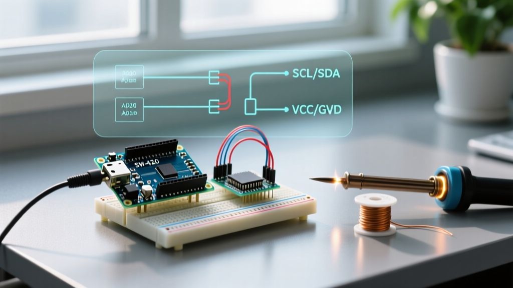
- Wire SDA to GPIO 8 and SCL to GPIO 9.
- Solder a 100µF electrolytic capacitor across the 3V3 and GND rails as close to the ESP32-S3 module as possible. This suppresses the ~350mA current spike when the Wi-Fi radio powers on, preventing brownout resets.
- Verify your I2C pull-ups. While the ESP32-S3 has internal pull-ups, they are roughly 45kΩ—too weak for reliable I2C communication at 400kHz. If your BME280 breakout doesn't have 4.7kΩ or 10kΩ surface-mount resistors on the SDA/SCL lines, add them externally.
Complete Firmware: MQTT & Deep Sleep
This code is written for the Arduino IDE using the esp32 board package by Espressif Systems (v3.0.x or newer). Select ESP32S3 Dev Module in the board manager. Ensure you have the Adafruit BME280 Library and PubSubClient installed via the Library Manager.
#include <WiFi.h>
#include <PubSubClient.h>
#include <Wire.h>
#include <Adafruit_BME280.h>

// --- PIN DEFINITIONS ---
#define I2C_SDA 8
#define I2C_SCL 9

// --- NETWORK & MQTT CONFIG ---
const char* ssid = "YOUR_WIFI_SSID";
const char* password = "YOUR_WIFI_PASSWORD";
const char* mqtt_server = "192.168.1.100"; // Your broker IP
const int mqtt_port = 1883;
const char* mqtt_topic = "home/environment/livingroom";

// --- SLEEP CONFIG ---
#define uS_TO_S_FACTOR 1000000ULL
#define TIME_TO_SLEEP  300 // 5 minutes

WiFiClient espClient;
PubSubClient client(espClient);
Adafruit_BME280 bme;

void setup() {
  Serial.begin(115200);
  delay(1000); // Allow serial monitor to attach

  // Initialize I2C with explicit pins and 400kHz clock
  Wire.begin(I2C_SDA, I2C_SCL, 400000);

  // Sensor Initialization with error handling
  if (!bme.begin(0x76, &Wire)) {
    Serial.println("[FATAL] Could not find a valid BME280 sensor, check wiring or I2C address!");
    // Go to sleep to save battery, will retry on next wake
    esp_deep_sleep(TIME_TO_SLEEP * uS_TO_S_FACTOR);
  }

  // Force sampling mode for deep sleep (forced mode)
  bme.setSampling(Adafruit_BME280::MODE_FORCED,
                  Adafruit_BME280::SAMPLING_X1, // Temp
                  Adafruit_BME280::SAMPLING_X1, // Pressure
                  Adafruit_BME280::SAMPLING_X1, // Humidity
                  Adafruit_BME280::FILTER_OFF);

  connectWiFi();
  client.setServer(mqtt_server, mqtt_port);

  if (connectMQTT()) {
    publishSensorData();
  }

  // Disconnect and sleep
  client.disconnect();
  WiFi.disconnect(true);
  WiFi.mode(WIFI_OFF);

  Serial.println("Going to sleep now...");
  esp_sleep_enable_timer_wakeup(TIME_TO_SLEEP * uS_TO_S_FACTOR);
  esp_deep_sleep_start();
}

void loop() {
  // Deep sleep resets the MCU; loop is never reached.
}

void connectWiFi() {
  Serial.print("Connecting to WiFi...");
  WiFi.mode(WIFI_STA);
  WiFi.begin(ssid, password);

  int attempts = 0;
  while (WiFi.status() != WL_CONNECTED && attempts < 40) {
    delay(500);
    Serial.print(".");
    attempts++;
  }

  if (WiFi.status() == WL_CONNECTED) {
    Serial.println(" Connected!");
  } else {
    Serial.println(" Failed!");
  }
}

bool connectMQTT() {
  if (WiFi.status() != WL_CONNECTED) return false;

  Serial.print("Attempting MQTT connection...");
  // Generate a semi-unique client ID
  String clientId = "ESP32S3-BME-" + String((uint32_t)ESP.getEfuseMac(), HEX);

  if (client.connect(clientId.c_str())) {
    Serial.println("connected");
    return true;
  } else {
    Serial.print("failed, rc=");
    Serial.print(client.state());
    return false;
  }
}

void publishSensorData() {
  // Take a forced reading
  bme.takeForcedMeasurement();

  float temp = bme.readTemperature();
  float humidity = bme.readHumidity();
  float pressure = bme.readPressure() / 100.0F; // Convert to hPa

  // Build JSON payload manually to avoid heavy ArduinoJson library overhead
  char payload[128];
  snprintf(payload, sizeof(payload), "{\"temp\":%.2f,\"hum\":%.2f,\"pres\":%.2f}", temp, humidity, pressure);

  if (client.publish(mqtt_topic, payload)) {
    Serial.println("Data published successfully.");
  } else {
    Serial.println("Publish failed.");
  }
}
Debugging: First Three Things to Check When It Fails
Embedded debugging requires a systematic approach. If your node fails to boot, connect, or publish, check these three areas in order.
1. I2C Bus Lockup or Sensor Not Found
Exact Error String: [E][Wire.cpp:499] requestFrom(): i2cRead returned 0 bytes or [FATAL] Could not find a valid BME280 sensor in the serial monitor.
Ranked Causes:
- Missing Pull-up Resistors: The ESP32-S3's internal pull-ups are too weak for the BME280's I2C interface at 400kHz. Add external 4.7kΩ resistors to SDA and SCL.
- Wrong I2C Address: The code assumes
0x76(CSB tied to 3V3). If your breakout board has CSB tied to GND, the address is0x77. Run an I2C scanner sketch to verify. - SDA/SCL Swapped: Unlike the original ESP32, the S3 does not automatically remap I2C pins if you swap them in hardware. Verify GPIO 8 is SDA and GPIO 9 is SCL.
2. Wi-Fi or MQTT Connection Timeout
Exact Error String: Attempting MQTT connection...failed, rc=-2 or WiFi.status() == 1 (WL_NO_SSID_AVAIL).
Ranked Causes:
- Broker Unreachable:
rc=-2means the TCP connection failed. Verify the MQTT broker IP is correct, port 1883 is open, and the ESP32 is on the same VLAN/subnet. - 2.4GHz Band Steering: The ESP32 only supports 2.4GHz Wi-Fi. If your router uses a unified SSID for 2.4/5GHz, the ESP32 may fail to associate. Create a dedicated 2.4GHz IoT SSID.
- Power Brownout: The Wi-Fi radio draws ~350mA during transmission. If your 3.3V LDO cannot supply this, the chip resets. Check for the
Brownout detector was triggeredpanic message.
3. Deep Sleep Wake Failure
Exact Error String: ESP-ROM: esp32s3-20210327; Build:chip723... (Continuous boot loops without executing setup).
Ranked Causes:
- Strapping Pin Interference: If GPIO 3, 45, or 46 are pulled high/low by external sensors during boot, the ESP32-S3 will enter download mode or fail to boot. Stick to safe GPIOs like 8 and 9.
- RTC Memory Corruption: If you are using RTC memory to persist variables across sleep, ensure you are using the
RTC_DATA_ATTRattribute correctly.
Extending and Simplifying the Build
Depending on your deployment environment, you may need to alter the architecture of this node.
If your sensor is deployed in a shed or garage where Wi-Fi signal is weak, drop the MQTT/Wi-Fi stack entirely. Use the ESP-NOW protocol. ESP-NOW allows the ESP32-S3 to transmit a payload directly to a receiving ESP32 (plugged into your router) in under 50ms, without associating with an access point. This reduces the Wi-Fi active time from ~4 seconds to ~50 milliseconds, dramatically extending battery life.
How to Extend:
- Add Light Sensing: Wire an Adafruit TSL2591 to the same I2C bus (it uses address 0x29). Ensure you add a decoupling capacitor for the new sensor.
- Local Display: Add a 1.54" e-ink display via SPI. E-ink draws zero power to maintain an image, making it ideal for deep-sleep nodes. Use GPIO 10-15 for the SPI bus.
- Over-The-Air (OTA) Updates: Integrate the
ArduinoOTAlibrary. Note that OTA requires the chip to stay awake longer to listen for mDNS broadcasts, which will increase your average current draw by roughly 15mA during the listening window.
FAQ: Common ESP 32 Projects Questions
Which ESP32 board variant is best for battery-powered ESP 32 projects?
For battery-powered builds, the ESP32-S3 or ESP32-C6 are the top choices in 2026. The S3 offers excellent deep-sleep currents (~7 µA) and dual-core performance for heavy payloads. The C6 is single-core but includes 802.15.4 (Zigbee/Thread) and Wi-Fi 6, making it ideal for ultra-low-power mesh networks. Avoid the original ESP32 (WROOM-32) for battery projects; its RTC controller draws significantly more current in deep sleep, and the Wi-Fi modem lacks the modern power-gating features of the S3/C6 silicon.
How do I prevent I2C sensor lockups in long-running ESP 32 projects?
I2C lockups usually occur when the ESP32 resets mid-transaction, leaving the SDA line pulled low by the sensor. To prevent this: (1) Always use external 4.7kΩ pull-up resistors. (2) Implement an I2C bus recovery routine in your setup() that toggles the SCL pin 9 times manually to force the slave to release the SDA line before calling Wire.begin(). (3) Use the watchdog timer (WDT) to reset the MCU if a sensor read hangs for more than 2 seconds.
Can I use the ESP32-C3 instead of the ESP32-S3 for simple ESP 32 projects?
Yes, the ESP32-C3 is an excellent, lower-cost alternative for simple nodes. It features a single-core RISC-V processor, Wi-Fi 4, and Bluetooth 5 (LE). It is pin-compatible with many ESP8266 designs and draws roughly 5 µA in deep sleep. However, it has fewer GPIOs (22 vs the S3's 45) and lacks the PSRAM found on N8R8 S3 modules. Choose the C3 if you only need to read a single I2C sensor and publish via MQTT; stick to the S3 if you need SPI displays, cameras, or complex local processing.