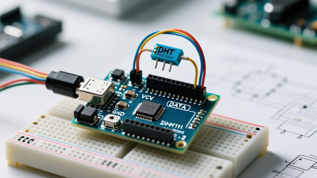
If you are wiring a DHT11 humidity sensor to a microcontroller, here is the direct answer: it outputs a proprietary digital single-bus signal (not analog, not I2C), requires a 4.7kΩ to 10kΩ pull-up resistor on the data line, and operates on a 3.3V to 5.5V supply. It resolves humidity in 1% increments and temperature in 1°C increments. While it is a staple in beginner kits, understanding its strict microsecond timing and 40-bit data structure is critical to preventing the infamous 'checksum failed' errors that plague most workbenches.
The DHT11 Sensing Principle and Output Type
The DHT11 measures relative humidity using a capacitive polymer dielectric. As ambient water vapor is absorbed by the polymer layer between two metal electrodes, the dielectric constant changes, altering the capacitance. An onboard ASIC measures this capacitance shift and converts it into a digital humidity value. For temperature, it relies on a surface-mounted NTC (Negative Temperature Coefficient) thermistor, which decreases in electrical resistance as ambient heat increases.
Crucially, the DHT11 output is strictly digital. It uses a proprietary single-bus protocol that resembles Dallas 1-Wire but is not electrically or logically compatible with it. A common beginner mistake is attempting to read the DATA pin with an analogRead() function; this will only yield noise. The sensor communicates by pulling the data line LOW and HIGH in precise microsecond intervals to transmit a 40-bit data packet. Because it is a single-bus digital protocol, you cannot connect multiple DHT11 sensors to the same data pin without complex multiplexing.
Wiring Pinout and Power Specifications
The bare DHT11 component has 4 pins, while the commonly sold breakout modules (like those from Keyestudio or HiLetgo) often have 3 pins because the NC (No Connect) pin is omitted and the pull-up resistor is pre-soldered onboard. Always verify your specific module before adding an external resistor.
| Pin | Name | Function & Wiring Target | Electrical Limits |
|---|---|---|---|
| 1 | VCC | Power Supply (Connect to 3.3V or 5V) | 3.3V to 5.5V DC |
| 2 | DATA | Digital I/O (Connect to MCU GPIO) | Requires 4.7kΩ - 10kΩ pull-up to VCC |
| 3 | NC | No Connect (Leave floating) | N/A |
| 4 | GND | Ground (Connect to MCU GND) | 0V Reference |
Numbered Wiring Steps for Arduino Uno
- Connect DHT11 Pin 1 (VCC) to the Arduino 5V pin.
- Connect DHT11 Pin 4 (GND) to the Arduino GND pin.
- Connect DHT11 Pin 2 (DATA) to Arduino Digital Pin 2.
- Insert a 4.7kΩ resistor between the DATA line (Pin 2) and the 5V rail. (Skip this if using a 3-pin pre-assembled module).
- Keep the wire length between the MCU and the sensor under 20 meters; for runs over 1 meter, drop the pull-up resistor value to 3.3kΩ to combat line capacitance.
Decoding the 40-Bit Data Stream: Raw-to-Unit Math
Unlike analog sensors where you map a 0-5V reading to a physical unit using a linear equation, the DHT11 handles the analog-to-digital conversion internally. The factory calibration coefficients are burned into the sensor's OTP (One-Time Programmable) memory. Therefore, no user scaling or calibration math is required. You only need to parse the raw bytes.
The MCU initiates communication by pulling the DATA line LOW for at least 18ms, then HIGH for 20-40µs. The DHT11 responds by pulling LOW for 80µs, then HIGH for 80µs. After this handshake, it clocks out 40 bits of data (MSB first). Here is the exact raw-to-unit byte structure:
- Byte 0: Relative Humidity Integer part (e.g., 45)
- Byte 1: Relative Humidity Decimal part (Always 0 on DHT11; used on DHT22)
- Byte 2: Temperature Integer part (e.g., 22)
- Byte 3: Temperature Decimal part (Always 0 on DHT11; Bit 8 is sign bit on some clones)
- Byte 4: Checksum
The Checksum Math
To verify data integrity, your code must sum the first four bytes and mask the result to 8 bits. If it does not match Byte 4, the reading is corrupt and must be discarded.
Checksum = (Byte0 + Byte1 + Byte2 + Byte3) & 0xFF
Example: If the sensor outputs 00101101 (45), 00000000 (0), 00010110 (22), 00000000 (0), the sum is 67. The checksum byte must also be 67 (01000011). The final physical units are simply 45% RH and 22°C.
Common Interference Sources and Bench Failures
If your serial monitor is spamming "Checksum Failed" or "Timeout," you are likely hitting one of three physical layer issues inherent to the DHT11's single-bus design.
- Microsecond Timing Violations (ISR Interference): The DHT11 protocol relies on pulse widths between 20µs and 70µs. If your microcontroller is servicing an interrupt (like a rotary encoder, a software serial port, or a WiFi stack on the ESP32) during the read cycle, the timing stretches. The MCU misinterprets a 70µs pulse as a 120µs pulse, reads a '1' instead of a '0', and the checksum fails. Fix: Disable interrupts (
noInterrupts()) immediately before triggering the sensor read, and re-enable them immediately after. - Self-Heating from Voltage Regulators: The onboard NTC thermistor is highly sensitive to localized heat. If you mount the DHT11 directly above an LM7805 linear regulator or a hot stepper motor driver on your PCB, the sensor will read 2°C to 4°C higher than ambient. Fix: Keep the sensor at least 2 inches away from heat-dissipating components, or use a remote wire harness.
- EMI and Capacitive Line Loading: Running the DATA wire parallel to AC mains or switching power supplies induces electromagnetic interference. Because the single-bus protocol lacks differential signaling or hardware error correction, EMI spikes flip bits in transit. Furthermore, long wires act as capacitors, rounding off the sharp digital square waves into slow curves. Fix: Use shielded cable for runs over 1 meter, and never route the data line next to 120V/240V AC lines.
Decision Matrix: DHT11 vs. Modern Alternatives
The DHT11 was designed over a decade ago as a low-cost educational tool. In 2026, modern I2C environmental sensors offer vastly superior accuracy, faster polling rates, and hardware-level error correction. Use the decision table below to select the right part for your bill of materials.
| Criteria | DHT11 | DHT22 (AM2302) | Bosch BME280 | Sensirion SHT31-D |
|---|---|---|---|---|
| Protocol | Proprietary 1-Wire | Proprietary 1-Wire | I2C / SPI | I2C |
| Humidity Accuracy | ± 5% RH | ± 2% RH | ± 3% RH | ± 2% RH |
| Temp Accuracy | ± 2°C | ± 0.5°C | ± 1.0°C | ± 0.3°C |
| Polling Rate | 1 Hz (1 sec delay) | 0.5 Hz (2 sec delay) | Up to 10 Hz | Up to 10 Hz |
| Avg. Cost (2026) | $1.00 - $1.50 | $3.50 - $5.00 | $4.00 - $7.00 | $6.00 - $9.00 |
| Best Use Case | Classroom blinking LEDs | Legacy greenhouse monitors | Weather stations, HVAC | Medical/precision incubators |
The Final Verdict and Concrete Pick
If your project requires logging data to an SD card, pushing to an MQTT broker, or triggering a relay based on a specific humidity threshold, do not use the DHT11. Its 1Hz polling rate and ±5% accuracy will result in missed transients and nuisance tripping.
Default Recommendation: Purchase the Bosch BME280 (specifically, the Adafruit part number ADA2652 or the SparkFun SEN-13676 breakout board). Priced around $5.50, it uses the standard I2C bus (eliminating the microsecond timing nightmares of the DHT11), includes a barometric pressure sensor for altitude/weather trending, and allows you to poll up to 10 times per second. Reserve the DHT11 strictly for introductory Arduino workshops where the primary goal is teaching basic digitalRead() timing concepts on a $1 budget.