
The Anatomy of a Blank Display: Why OLEDs Fail
There are few things more frustrating in embedded prototyping than uploading a perfectly compiled sketch to your microcontroller, only to be greeted by the abyss of a completely black, unresponsive display. The Arduino OLED screen—most commonly the 0.96-inch 128x64 I2C variant—is a staple in DIY electronics. Yet, despite its popularity, it remains a frequent source of hardware and software headaches for both beginners and seasoned engineers.
When an OLED fails to initialize, the root cause is rarely a 'dead' panel. Instead, the failure usually stems from one of four distinct domains: power delivery instability, I2C bus impedance mismatches, silent chipset driver conflicts, or SPI protocol misconfigurations. In this comprehensive diagnostic guide, we will bypass generic advice and dive deep into the electrical and architectural realities of OLED troubleshooting, utilizing phased diagnostics to isolate and resolve your display issues.
Phase 1: Power Delivery & Decoupling Diagnostics
The most overlooked cause of a blank or flickering Arduino OLED screen is inadequate power delivery. OLED panels do not draw a constant current; they draw high-frequency current spikes when illuminating large blocks of white pixels. If your power rail cannot respond to these transient demands, the internal charge pump of the display driver will brownout, resetting the controller mid-frame.
The 0.1µF vs 10µF Capacitor Rule
Most cheap breakout boards include a microscopic 0.1µF ceramic decoupling capacitor near the VCC pin. While this handles high-frequency noise, it is entirely insufficient for the macro-level current spikes of an OLED matrix. The Fix: Solder an additional 10µF to 47µF electrolytic or tantalum capacitor directly across the VCC and GND header pins on your breakout board. This local energy reservoir prevents voltage sag during heavy pixel rendering.
The 3.3V LDO Trap on Clone Boards
Many generic I2C OLED modules advertise '5V compatibility' via an onboard 3.3V Low Dropout Regulator (LDO). However, to cut costs, some manufacturers omit the LDO entirely or use a counterfeit chip that drops out at 4.2V. If you are powering the module from an Arduino Uno's 5V pin and the screen remains dead, use a multimeter to probe the actual VCC pin on the display side of the LDO. If it reads below 3.0V, bypass the onboard regulator and power the display directly from the Arduino's 3.3V pin, provided your specific module's logic lines are 3.3V tolerant.
Phase 2: I2C Bus Impedance & Logic Level Shifting
The I2C protocol relies on open-drain outputs. This means the microcontroller and the OLED screen can only pull the SDA and SCL lines LOW; they require external pull-up resistors to bring the lines HIGH.
Verifying Pull-Up Resistor Values
Standard Arduino OLED breakouts include 4.7kΩ or 10kΩ surface-mount pull-up resistors tied to VCC. If you have multiple devices on the same I2C bus (e.g., an OLED, a BME280 sensor, and an RTC module), the parallel resistance drops significantly. A combined pull-up resistance below 2kΩ can cause the I2C bus to fail to reach the logic HIGH threshold, resulting in a blank screen. Use a multimeter in resistance mode (with power disconnected) to measure the resistance between SDA and VCC. If it is under 3kΩ, you must physically desolder the pull-up resistors from the peripheral modules, leaving only one set on the bus.
5V Logic vs 3.3V OLED Degradation
While the SSD1306 controller is somewhat tolerant of 5V logic on the I2C lines, prolonged exposure to 5V from an Arduino Uno or Mega will degrade the internal ESD protection diodes. Over time, this causes 'clock stretching' failures where the display holds the SCL line low indefinitely. For long-term reliability, always use a BSS138 bidirectional logic level shifter between your 5V Arduino and the 3.3V OLED I2C lines.
Phase 3: The Silent Killer: SSD1306 vs. SH1106 Mismatches
If your I2C scanner successfully finds the display, but the screen remains black or shows a shifted, corrupted image, you are likely a victim of a chipset bait-and-switch.
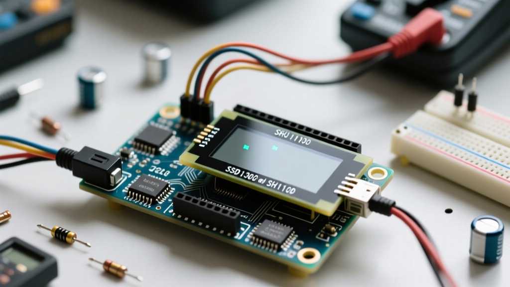
Expert Insight: Many 1.3-inch OLEDs sold on AliExpress and Amazon are listed as 'SSD1306 Compatible'. In reality, they utilize the SH1106 driver. The SSD1306 has a 128x64 internal RAM buffer, while the SH1106 has a 132x64 buffer. Sending SSD1306 initialization commands to an SH1106 chip will result in a blank screen or a display that is offset by 4 pixels.
Resolving Driver Conflicts with U8g2
To eliminate driver guesswork, abandon the basic Adafruit_SSD1306 library and migrate to the U8g2 Library Wiki, which maintains an exhaustive database of clone and variant chipsets. When initializing your display, select the exact constructor for your hardware. For example, if you have an SH1106, your constructor should look like this:
U8G2_SH1106_128X64_NONAME_F_HW_I2C u8g2(U8G2_R0, U8X8_PIN_NONE);
This ensures the correct memory mapping and initialization sequence is sent to the silicon.
Phase 4: I2C Address Conflicts & Scanner Tools
The I2C address of an Arduino OLED screen is hardcoded by the manufacturer, typically determined by the state of the SA0 (or D/C) pin on the silicon.
| Display Variant | Typical Driver | Default I2C Address | Alternative Address |
|---|---|---|---|
| 0.91" 128x32 I2C | SSD1306 | 0x3C | N/A |
| 0.96" 128x64 I2C | SSD1306 | 0x3C | 0x3D |
| 1.3" 128x64 I2C | SH1106 | 0x3C | 0x3D |
| 1.5" 128x128 I2C | SSD1327 | 0x3D | 0x3C |
Upload the standard Arduino I2C Scanner sketch (available via the Arduino I2C Communication Documentation). If the serial monitor outputs No I2C devices found, your issue is strictly hardware (wiring, broken traces, or dead pull-ups). If it outputs 0x3C but the screen is blank, your issue is software (wrong library, wrong constructor, or missing initialization sequence).
Phase 5: SPI Protocol Specific Failures
If you are using the 7-pin SPI version of the Arduino OLED screen, the troubleshooting matrix changes entirely. SPI is significantly faster than I2C but requires precise GPIO mapping.
The D/C (Data/Command) Pin Criticality
The most common SPI wiring error is misidentifying the D/C (Data/Command) pin. This pin tells the OLED whether the incoming SPI byte is a configuration command (e.g., 'set contrast') or pixel data. If you accidentally wire the D/C pin to the wrong Arduino GPIO, or if you forget to define it in your software constructor, the display will interpret pixel data as commands. This usually results in a screen filled with white noise, random static, or a completely black display that refuses to clear.
Clock Polarity and Phase (CPOL/CPHA)
The SSD1306 SPI interface requires specific clock polarity and phase settings. According to the Adafruit Monochrome OLED Breakouts Guide, the SPI bus must be configured for Mode 0 (CPOL=0, CPHA=0). If you are using a custom SPI library or a non-AVR microcontroller (like an ESP32 or STM32) alongside your Arduino environment, ensure the SPI bus is not being reconfigured to Mode 3 by another peripheral, such as an SD card module, which will instantly halt OLED communication.
Advanced Diagnostics: Using a Logic Analyzer
When multimeters and software scanners fail, a logic analyzer (such as a Saleae Logic or a cheap 8-channel Cypress FX2 clone) is the ultimate truth-teller. Hook up the analyzer to the SDA and SCL lines and trigger on the falling edge of SCL.
- Missing ACK Bits: If the Arduino sends the address byte (0x78 for 0x3C) but the 9th clock cycle (the ACK bit) remains HIGH, the OLED is not acknowledging. This confirms a dead panel, a severed ground trace, or a voltage brownout.
- Clock Stretching: If the SCL line is held LOW by the OLED for an extended period, the display's internal charge pump is failing to initialize, usually due to a missing or failed external boost capacitor on the breakout board.
Summary Checklist for Rapid Recovery
- Verify VCC voltage under load with a multimeter (must be >3.1V).
- Run the I2C Scanner sketch to confirm bus visibility.
- Measure parallel pull-up resistance if multiple I2C devices are present.
- Confirm whether your silicon is SSD1306, SH1106, or SSD1327.
- Switch to the U8g2 library and select the exact hardware constructor.
- For SPI, verify the D/C pin mapping and ensure SPI Mode 0 is enforced.
By systematically isolating the power, bus impedance, and driver architecture, you can resurrect almost any 'dead' Arduino OLED screen and return to building robust, visually rich embedded projects.