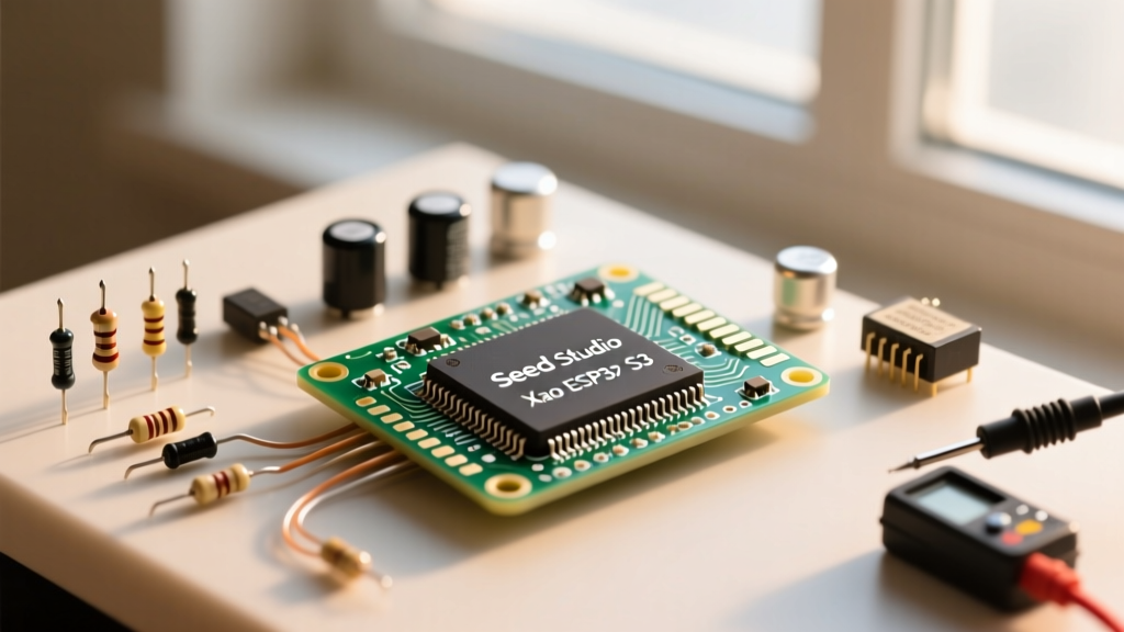

The Seeed Studio Xiao ESP32 S3 has rapidly become a favorite in the maker community for ultra-compact IoT, wearable, and edge-AI projects. Measuring just 21 x 17.5mm, it packs the dual-core 240MHz ESP32-S3 chip into a footprint smaller than a postage stamp. However, its diminutive size and native USB architecture introduce unique hardware quirks that frequently trip up both beginners and seasoned engineers.
This comprehensive FAQ and quick reference guide addresses the most common troubleshooting scenarios, pinout limitations, and power management realities of the Xiao ESP32 S3, ensuring your next deployment is flawless.
Core Specifications at a Glance
Before diving into troubleshooting, it is critical to understand the exact silicon you are working with. The Xiao ESP32 S3 is built around the ESP32-S3R8 variant.
| Feature | Specification |
|---|---|
| Microcontroller | ESP32-S3R8 (Dual-core Xtensa LX7 @ 240MHz) |
| Memory | 512KB SRAM |
| Storage | 8MB Flash |
| PSRAM | 8MB (Octal SPI) |
| Wireless | Wi-Fi 4 (802.11 b/g/n), Bluetooth 5.0 (BLE) |
| Logic Voltage | 3.3V (Strictly NOT 5V tolerant) |
| GPIO Count | 11 usable digital/analog pins |
Arduino IDE Setup and PSRAM Configuration
A frequent source of compilation errors stems from incorrect board manager configurations. To program the Xiao ESP32 S3, you must use the official Espressif Arduino Core.
- Navigate to File > Preferences and add the Espressif JSON URL:
https://raw.githubusercontent.com/espressif/arduino-esp32/gh-pages/package_esp32_index.json - Open the Board Manager, search for
esp32, and install the latest stable release. - Select XIAO_ESP32S3 from the boards list.
Critical E-E-A-T Insight: To utilize the full 8MB of onboard PSRAM for camera buffers or audio processing, you must navigate to Tools > PSRAM and select OPI PSRAM. Leaving this on 'Disabled' or 'QSPI' will artificially cap your available memory and cause runtime allocation crashes.
The Native USB & Serial Monitor Trap
Unlike the NodeMCU or older ESP32 DevKits, the Xiao ESP32 S3 does not feature a dedicated UART-to-USB bridge chip (like the CP2102 or CH340). It relies on the ESP32-S3's native USB peripheral.
The Problem: You upload your sketch successfully, but the Serial Monitor remains completely blank.
The Fix: In the Arduino IDE Tools menu, you must set USB CDC On Boot to Enabled. If this is disabled, the Serial.begin() command routes to the hardware UART pins (D6/D7) rather than the USB-C port. Additionally, add a while(!Serial) { delay(10); } loop in your setup() function to pause execution until the Serial Monitor is actually opened on your PC.
Bootloader Entry: The Button Dance
Because the native USB bootloader can sometimes hang or fail to auto-reset during a failed flash attempt, you must know how to manually force the Xiao ESP32 S3 into download mode. The board features a tiny Reset (R) button and a Boot (B) button on the side of the PCB.
Manual Bootloader Sequence
- Press and hold the Boot (B) button.
- While holding Boot, press and release the Reset (R) button.
- Release the Boot (B) button.
- The board is now in ROM bootloader mode. Click 'Upload' in the Arduino IDE.
- Once flashing reaches 100%, press the Reset (R) button once to execute the new sketch.
Pinout Logic, Voltage Tolerances, and Mapping
The most common hardware failure mode for the Xiao ESP32 S3 is feeding 5V logic into its GPIO pins. The ESP32-S3 silicon is strictly 3.3V. Exceeding 3.6V on any GPIO will permanently degrade or destroy the input latch.
| Xiao Pin | GPIO Number | Primary Function | Notes |
|---|---|---|---|
| D0 | GPIO1 | Analog / Digital | ADC1 channel, safe for deep sleep wake |
| D1 | GPIO2 | Analog / Digital | ADC1 channel |
| D2 | GPIO3 | Analog / Digital | ADC1 channel |
| D3 | GPIO4 | Analog / Digital | ADC1 channel |
| D4 | GPIO5 | I2C SDA | Default Wire SDA |
| D5 | GPIO6 | I2C SCL | Default Wire SCL |
| D6 | GPIO43 | UART TX | Default Serial1 TX |
| D7 | GPIO44 | UART RX | Default Serial1 RX |
| D8 | GPIO7 | SPI SCK | Default SPI Clock |
| D9 | GPIO8 | SPI MISO | Default SPI MISO |
| D10 | GPIO9 | SPI MOSI / CS | Often used as Chip Select |
For complete schematic details and absolute maximum ratings, always refer to the official ESP32-S3 datasheet.
Antenna Selection: PCB vs. U.FL Modification
The Xiao ESP32 S3 ships with both an onboard stamped PCB antenna and a U.FL connector for an external antenna. However, they are not active simultaneously. By default, the PCB antenna is enabled via a 0-ohm surface-mount resistor.
If your project is housed in a metal enclosure or requires extended range, you must switch to the U.FL connector. This requires a steady hand and a hot air rework station or fine-tipped soldering iron:
- To use the U.FL connector: Desolder the 0-ohm resistor from the 'PCB' pad and move it to the 'U.FL' pad located just millimeters away.
- Warning: Never transmit Wi-Fi or BLE without an antenna attached. The reflected RF energy can damage the ESP32-S3's internal power amplifier.
Powering the Board and Deep Sleep Realities
Power management on the Xiao ESP32 S3 requires understanding its three power input paths:
- USB-C Port (5V): Regulated down to 3.3V by the onboard LDO.
- 5V Pin: Tied directly to the USB VBUS. Use this to power external 5V peripherals, but do not draw more than 500mA.
- Battery Pads (BAT+ / BAT-): Located on the rear of the PCB. Supports 3.7V LiPo batteries directly. The board includes a built-in charging IC that charges the battery when USB is connected.
Deep Sleep Current Optimization
When properly configured using esp_deep_sleep_start(), the Xiao ESP32 S3 can achieve a deep sleep current of approximately 14 µA. To hit this metric, you must ensure all internal pull-ups are disabled, the Wi-Fi/BLE radios are explicitly powered down via esp_wifi_stop(), and the PSRAM is put into standby mode before triggering the sleep sequence. For advanced power topologies, consult the Seeed Studio XIAO ESP32S3 Wiki.
XIAO ESP32S3 vs. XIAO ESP32S3 Sense: Clearing the Confusion
A frequent point of confusion in maker forums is camera compatibility. The base Xiao ESP32 S3 (green PCB) does not have a camera connector or an SD card slot. If your project requires computer vision, QR code scanning, or timelapse photography, you must purchase the Xiao ESP32S3 Sense variant. The Sense version includes a detachable expansion board featuring an OV2640 camera interface and a microSD card slot, utilizing the ESP32-S3's dedicated LCD/Camera interface pins. For setting up the Arduino ESP32 Camera library with the Sense expansion, ensure you map the specific XIAO camera pins defined in the Seeed documentation, as they differ from the standard ESP-EYE pinouts.