
Transitioning an Arduino project from a USB-tethered breadboard prototype to a standalone, field-deployed device is a critical milestone for any maker or engineer. During the prototyping phase, relying on USB power is convenient. However, when your project requires mobility, higher current draw, or 24/7 reliability, USB power falls short. This is where the VIN Arduino pin becomes the cornerstone of your power architecture. In this comprehensive migration and upgrade guide, we will explore how to safely transition to external DC power via the VIN pin, the thermal limitations of onboard regulation, and the modern 2026 upgrade paths for high-efficiency deployments.
The Prototyping Trap: Why USB Power Fails in Deployment
Most developers begin their journey powering their microcontroller via the USB-B or USB-C port. While excellent for serial debugging and sketch uploading, USB power is fundamentally limited. A standard USB 2.0 port provides a maximum of 500mA, and many unpowered hubs or laptop ports sag well below this under transient loads. Furthermore, relying on a physical USB cable for permanent installations introduces mechanical fragility and ground-loop noise issues.
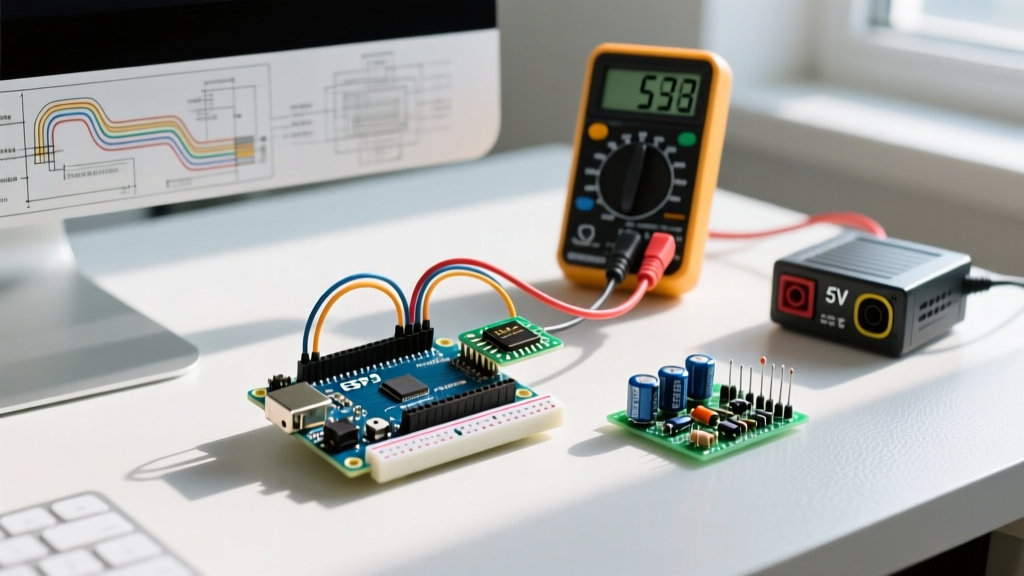
Migrating to the VIN (Voltage Input) pin allows you to supply an unregulated DC voltage (typically between 7V and 12V) from a battery pack, solar charge controller, or AC-to-DC wall adapter. The board's onboard circuitry then steps this down to a clean 5V logic level. However, this migration is not as simple as plugging in a 12V battery; it requires a deep understanding of linear regulation and thermal management.
Understanding the VIN Arduino Architecture
When you supply voltage to the VIN pin on a standard board like the Arduino Uno Rev3, the current passes through a reverse-polarity protection diode (typically a 1N4007 or equivalent surface-mount M7 diode) and then into the onboard 5V linear regulator. On most genuine and high-quality clone boards, this regulator is an NCP1117ST50T3G or an LM1117-5.0 housed in a SOT-223 package.
Engineering Note: The VIN pin is directly connected to the input of the onboard 5V voltage regulator. It is not a raw passthrough to the microcontroller. The regulator requires a minimum "dropout voltage" to maintain a stable 5V output. For the NCP1117, this dropout is approximately 1.1V to 1.3V at full load. Therefore, an absolute minimum of 6.3V is required at the VIN pin, though 7V is the recommended practical minimum to account for diode voltage drops and transient sags.
Step-by-Step Migration: Calculating Thermal Headroom
The most common failure mode when migrating to VIN power is thermal shutdown of the onboard linear regulator. Linear regulators operate by burning off excess voltage as heat. To design a reliable system, you must calculate the power dissipation ($P_d$).
The Thermal Dissipation Formula
The heat generated by the regulator is calculated as:
$P_d = (V_{in} - V_{out}) \times I_{load}$
Let us examine a real-world scenario. Suppose you are powering an Arduino Uno via the VIN pin with a 12V lead-acid battery, and your circuit (including sensors and an LCD shield) draws 200mA (0.2A) from the 5V rail.
- Voltage Drop: 12V - 5V = 7V
- Power Dissipated: 7V × 0.2A = 1.4 Watts
According to the Texas Instruments LM1117 datasheet, the SOT-223 package has a junction-to-ambient thermal resistance ($\theta_{JA}$) of approximately 50°C/W (assuming standard PCB copper pour). A 1.4W dissipation results in a temperature rise of 70°C above ambient. In a 25°C room, the regulator junction will reach 95°C. While this is below the typical 150°C thermal shutdown threshold, the regulator will be too hot to touch, and system reliability will degrade over time.
Power Architecture Comparison Matrix
When planning your migration, it is vital to compare the available power routing options. The table below outlines the operational characteristics of each method as of modern 2026 deployment standards.
| Power Method | Input Voltage | Efficiency | Max Safe Current (5V Rail) | Heat Generation | Best Use Case |
|---|---|---|---|---|---|
| USB Port | 5.0V DC | High (~95%) | 500mA (Host dependent) | Negligible | Desktop prototyping, serial debugging |
| 5V Pin (Direct) | 4.8V - 5.5V | 100% (Bypasses regulator) | 1A+ (Depends on external PSU) | None on board | Custom PCBs, external buck converters |
| VIN Pin (Linear) | 7V - 12V DC | Low (40% - 70%) | ~300mA (at 9V input) | High | Low-power battery packs, simple wall adapters |
| VIN Pin (External Buck) | 7V - 9V DC | High (~85%) | 1A+ (Regulator barely loaded) | Very Low | High-current IoT, robotics, motor drivers |
The 2026 Upgrade Path: Integrating External DC-DC Buck Converters
As maker projects in 2026 increasingly incorporate high-draw peripherals like LiDAR sensors, 5V servo arrays, and cellular modems, relying on the onboard linear regulator via the VIN pin is no longer viable for loads exceeding 300mA. The ultimate upgrade path is to use an external switching regulator (buck converter).
Why Switching Regulators Win
Unlike linear regulators that burn excess voltage as heat, switching regulators rapidly pulse the input voltage and use inductors to step it down, achieving efficiencies of 85% to 95%. As detailed in the Pololu Voltage Regulator Guide, switching regulators are mandatory for high-current, battery-operated deployments where thermal management and battery life are paramount.
Recommended Hardware: The MP1584EN Module
For most migration projects, the MP1584EN-based buck converter modules (widely available for $2.00 to $4.00) offer an exceptional balance of cost, size, and performance. They can handle up to 3A of continuous current and accept input voltages up to 28V.
Wiring the Upgrade: VIN vs. 5V Pin
When integrating an external buck converter, you have two distinct architectural choices:
- The VIN Injection Method: Set the buck converter output to 7.5V or 8.0V and wire it to the Arduino's VIN pin. This utilizes the onboard reverse-polarity diode and keeps the board's auto-power-selection circuitry intact. However, the onboard linear regulator still handles the final 7.5V-to-5V drop, meaning it still generates some heat.
- The 5V Pin Bypass Method (Expert Choice): Set the buck converter output to exactly 5.0V and wire it directly to the Arduino's 5V pin. This completely bypasses the inefficient onboard linear regulator. Warning: You must ensure the output is precisely 5.0V (never exceed 5.5V) and ensure you never connect USB power simultaneously, as this will back-feed 5V into the USB host, potentially damaging your computer.
Expert Troubleshooting: Common VIN Migration Failures
Even with careful planning, migrating to external DC power via the VIN pin can introduce edge-case failures. Here is how to diagnose the most common issues encountered in the field.
1. Brownout Resets Under Transient Loads
Symptom: The Arduino randomly resets or the serial monitor outputs garbage characters when a peripheral (like a relay or servo) activates.
Root Cause: Voltage sag. If your external 9V battery has a high internal resistance, a sudden 500mA current spike can cause the battery voltage to temporarily drop below the 6.3V dropout threshold of the NCP1117 regulator.
Solution: Add a low-ESR (Equivalent Series Resistance) electrolytic capacitor (e.g., 470µF, 25V) directly across the VIN and GND pins at the Arduino header to supply transient current spikes.
2. The "Hot Regulator" Thermal Throttle
Symptom: The board works fine for 10 minutes, then shuts down or behaves erratically. Touching the voltage regulator near the DC jack reveals it is burning hot.
Root Cause: The internal thermal protection circuitry of the LM1117/NCP1117 is tripping at ~150°C junction temperature.
Solution: Lower the input voltage. If you are using a 12V adapter, switch to a 7.5V or 9V adapter. Halving the voltage differential ($V_{in} - 5V$) instantly halves the thermal dissipation, bringing the regulator back into a safe operating area without requiring a heatsink.
3. Back-Feeding Through the USB Port
Symptom: When powered via VIN, the Arduino's USB port shows 5V on its VBUS line, and connected laptops report a "USB Over Current" error.
Root Cause: A faulty or bypassed polyfuse (resettable PTC) on the Arduino board, or a modification made to the 5V rail that is back-feeding the USB VBUS line.
Solution: Verify the integrity of the onboard 500mA resettable polyfuse located near the USB port. If deploying in a harsh environment where back-feeding is a risk, physically sever the VBUS trace on the underside of the PCB or use a USB isolator module.
Conclusion: Designing for the Field
Migrating your project to use the VIN Arduino pin is a rite of passage from hobbyist prototyping to professional embedded deployment. By understanding the thermal constraints of the onboard linear regulator, calculating your exact power dissipation, and knowing when to upgrade to an external MP1584EN buck converter, you ensure your microcontroller remains stable in the real world. Whether you are building an off-grid weather station or an autonomous rover, mastering your power architecture is the foundation of reliable electronics design.