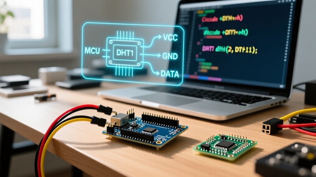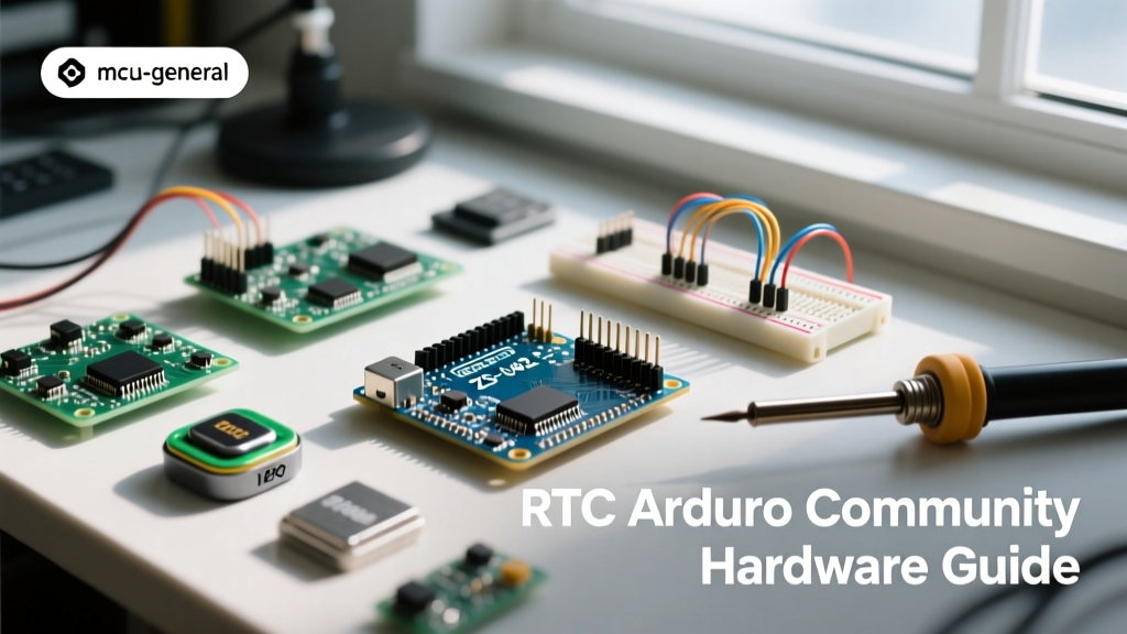

When integrating an RTC Arduino setup into your next data logger, smart home controller, or automated greenhouse, the hardware you choose and the code you write can mean the difference between a reliable deployment and a failed project. Over the past decade, the maker community has rigorously tested, broken, and optimized Real-Time Clock (RTC) modules. What started with the notoriously inaccurate DS1307 has evolved into a mature ecosystem of temperature-compensated oscillators and sophisticated open-source libraries. This guide synthesizes years of forum debates, GitHub issues, and teardown analyses into a definitive community resource for Arduino timekeeping.
The Community Consensus: DS1307 vs. DS3231 vs. PCF8523
If you ask any veteran maker on the Arduino forums which RTC module to buy, the answer is almost universally the DS3231. But understanding why requires looking at the silicon. The older DS1307 relies on an external 32.768kHz tuning fork crystal. These crystals are highly sensitive to temperature fluctuations, leading to drift rates of up to ±2 seconds per day. In a month, your data logger's timestamp could be off by a full minute—unacceptable for scientific or industrial logging.
The DS3231, however, integrates a Temperature-Compensated Crystal Oscillator (TCXO) directly into the chip package. By continuously measuring the ambient die temperature and adjusting the oscillator's load capacitance via an internal varactor, the DS3231 achieves an accuracy of ±2ppm (parts per million). This translates to roughly ±1 minute of drift per year. According to the Analog Devices DS3231 Datasheet, the chip handles the thermal compensation internally, requiring zero calibration code from the user.
While the NXP PCF8523 offers a solid middle ground with slightly better drift than the DS1307 and lower power consumption, the market economics have shifted. Generic DS3231 breakout boards are now mass-produced at such high volumes that they frequently cost less than PCF8523 alternatives, cementing the DS3231 as the undisputed community standard for 5V and 3.3V microcontroller ecosystems.
The ZS-042 Module Warning: A Community Rite of Passage
No community resource on this topic is complete without addressing the infamous ZS-042 RTC module. If you purchase a DS3231 breakout board from Amazon, AliExpress, or eBay for under $5, it is almost certainly a ZS-042 or a clone thereof. While the silicon on these boards is usually genuine, the power management circuit designed for the backup battery contains a dangerous flaw that has destroyed countless projects.
The ZS-042 module includes a charging circuit consisting of a 200-ohm resistor and a 1N4148 diode in series between the VCC pin and the battery positive terminal. This circuit was designed to trickle-charge an LIR2032 (a 3.6V rechargeable lithium-ion coin cell). However, LIR2032 batteries have very low capacity (roughly 35mAh) and are hard to source locally. Most makers naturally substitute a standard CR2032 (a 3.0V non-rechargeable lithium coin cell with 225mAh capacity).
Community Safety Alert: Applying a 5V VCC to a ZS-042 module with a CR2032 installed forces reverse current into the non-rechargeable battery. This causes the battery to heat up, vent toxic gases, and potentially rupture or explode, damaging your microcontroller and posing a fire hazard.
The Community Fix: Before soldering headers to your ZS-042 module, locate the small diode and resistor near the battery holder. You have three options: desolder the diode, snip the diode's leg with flush cutters, or use an X-Acto knife to sever the PCB trace connecting the charging circuit to the battery pin. Once disabled, the module will safely rely on the CR2032 purely for backup power when VCC is removed, drawing only microamps from the cell.
Wiring for Stability: I2C Bus Capacitance and Pull-Ups
The DS3231 communicates via the I2C protocol (address 0x68). While the Arduino Wire library abstracts the low-level bit-banging, physical bus topology remains a frequent point of failure in complex builds. The I2C bus is open-drain, meaning it requires pull-up resistors to pull the SDA and SCL lines HIGH.
Many cheap RTC modules include 4.7kΩ surface-mount pull-up resistors tied to VCC. If you are connecting multiple I2C devices (e.g., an RTC, a BME280 sensor, and an OLED display), the parallel resistance of these onboard pull-ups can drop the total bus resistance too low, exceeding the I2C sink current limit (typically 3mA) and causing data corruption or bus lockups. Furthermore, long jumper wires add parasitic capacitance to the bus. If your total wire length exceeds 30cm, the community recommends removing the pull-ups from the slave modules and installing a single pair of 2.2kΩ or 4.7kΩ pull-up resistors directly at the Arduino's SDA/SCL pins to ensure crisp signal edges.
Software Stack: Choosing the Right Library
Hardware is only half the battle; parsing BCD (Binary-Coded Decimal) registers and handling leap years is tedious. The community has largely standardized around two primary libraries for RTC Arduino integration:
- Adafruit RTClib: The undisputed champion for general-purpose timekeeping. As documented in the RTClib GitHub repository, it elegantly handles DateTime objects, Unix time conversions, and spans (time deltas). It is highly recommended for 90% of projects, especially those involving SD card data logging where human-readable timestamps are required.
- DS3232RTC by Jack Christensen: Preferred by advanced users building low-power, battery-operated devices. This library exposes the DS3231's internal alarm registers and interrupt pins much more cleanly than RTClib, making it the go-to choice for projects that require the RTC to wake a sleeping microcontroller.
Community Troubleshooting Matrix
When your serial monitor spits out garbage data or the year reads '2165', consult this community-compiled troubleshooting matrix before assuming your chip is dead.
| Symptom | Root Cause | Community-Verified Fix |
|---|---|---|
| Year reads 2165 or 2000 | OSC Stop Flag (OSF) is set; oscillator halted due to dead battery. | Run rtc.adjust(DateTime(F(__DATE__), F(__TIME__))) to clear the flag and reset time. |
| I2C Scanner finds no device | Missing pull-up resistors or SDA/SCL swapped. | Verify 4.7k pull-ups to 3.3V/5V. Check pinout (some clones swap SDA/SCL silkscreen). |
| Time drifts by minutes daily | Using a DS1307 instead of DS3231, or counterfeit DS3231 chip. | Verify chip markings. Genuine DS3231 has a laser-etched logo; fakes often use painted text. |
| Time resets on power cycle | CR2032 battery depleted or ZS-042 charging circuit destroyed it. | Measure battery voltage under load. Replace battery and disable charging circuit. |
Leveraging the SQW Pin for Low-Power Data Logging
For off-grid environmental monitors, power consumption is the ultimate bottleneck. An Arduino Uno left running 24/7 will drain a 18650 lithium cell in a matter of days. The community's standard approach to extending battery life to months or years involves putting the ATmega328P into deep sleep and using the DS3231's SQW/INT pin to wake it.
By configuring Alarm 1 on the DS3231, the RTC can pull the SQW pin LOW at a specific minute and second. This hardware interrupt triggers the Arduino's wake-up vector. Immediately upon waking, the sketch reads the sensors, logs the data to an SD card, and commands the microcontroller back to sleep. Crucially, you must disable the DS3231's internal 32kHz square wave output and ensure the alarm interrupt flag is cleared via I2C after waking, otherwise the SQW pin will remain LOW, and the Arduino will immediately wake up again, creating an infinite power-draining loop.
By respecting the hardware quirks of mass-produced modules, implementing proper I2C bus hygiene, and leveraging community-maintained libraries, your RTC Arduino project will achieve the precise, reliable timekeeping required for professional-grade maker deployments.