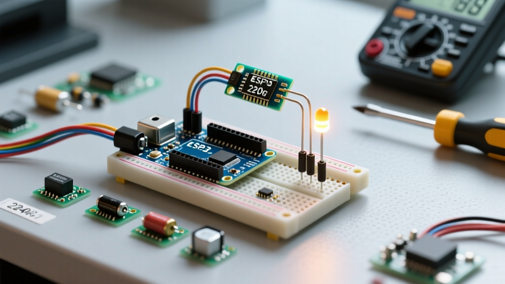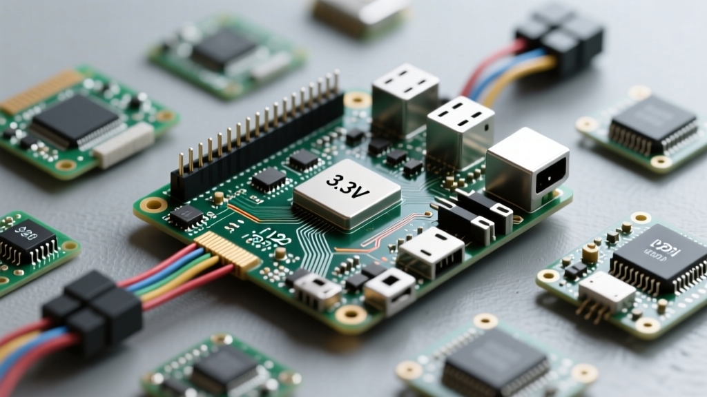

Transitioning from the forgiving 5V world of Arduino to the Raspberry Pi ecosystem requires a fundamental shift in how you approach hardware interfaces. The raspi pinout is incredibly versatile, but its strict 3.3V logic tolerance means a single miswired 5V sensor can permanently destroy your Broadcom SoC. This compatibility guide bridges the gap between microcontrollers and single-board computers, detailing exact bus mappings, voltage translation strategies, and hardware limitations for makers integrating diverse components.
The 3.3V vs 5V Logic Divide: Core Compatibility Rules
Unlike the ATmega328P on an Arduino Uno, which operates natively at 5V, the Raspberry Pi's GPIO header operates strictly at 3.3V. Feeding a 5V logic HIGH into any standard GPIO pin (such as GPIO 17 or 27) will likely fry the internal ESD protection diodes and destroy the pin, or worse, the entire CPU.
Voltage Translation Strategies
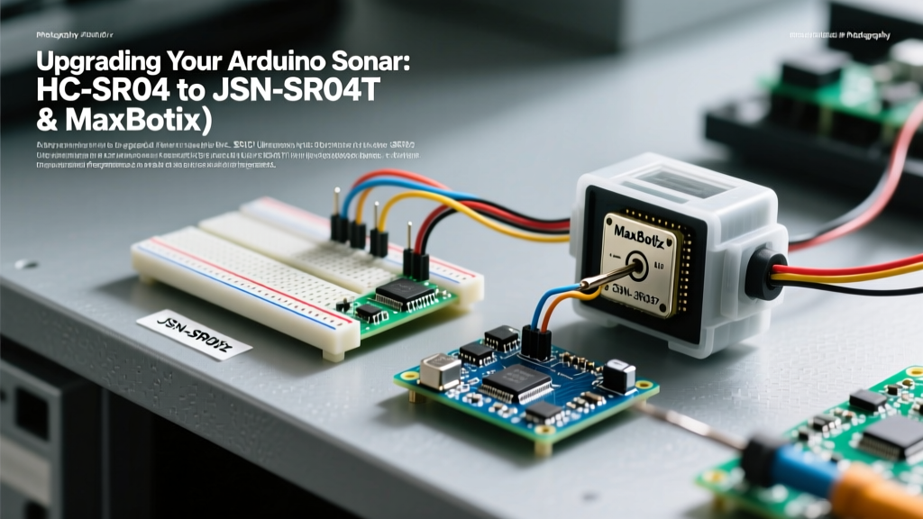
When wiring 5V modules (like the ubiquitous HC-SR04 ultrasonic sensor or standard 16x2 LCDs) to the raspi pinout, you must step down the voltage. You have two primary options:
- Dedicated Logic Level Converters: Using a chip like the TXB0108 or a MOSFET-based module (BSS138) is the safest route for bidirectional buses like I2C. SparkFun's guide on logic levels provides an excellent deep dive into MOSFET translation circuits.
- Resistor Voltage Dividers: For unidirectional signals (e.g., the Echo pin of an HC-SR04 to the Pi), a simple voltage divider works perfectly. Using a 1kΩ resistor (R1) in series and a 2kΩ resistor (R2) to ground will drop a 5V signal to a safe 3.33V.
Expert Warning: Never rely on internal software pull-up resistors to handle 5V overvoltage. The Pi's internal clamping diodes are only rated to handle microamps of leakage, not the sustained milliamp output of a standard 5V sensor module.
Power Pin Mapping & Current Limits
The 40-pin header provides access to the 5V and 3.3V power rails, but they are not designed to power high-draw peripherals. On the Raspberry Pi 4 and 5, the 3.3V rail is generated by an onboard switching regulator with a strict maximum current limit, typically around 800mA shared across the entire board's 3.3V logic.
| Pin Type | Physical Pins | Max Safe Current | Best Use Case |
|---|---|---|---|
| 3.3V Power | 1, 17 | ~50mA per pin | Powering low-draw I2C sensors, logic level shifters |
| 5V Power | 2, 4 | Limited by USB-C PSU | Powering servos, LED strips (with separate GND returns) |
| GPIO (Logic) | All BCM pins | 16mA per pin / 50mA total bank | Signaling, triggering MOSFETs, SPI/I2C data |
Communication Bus Pinouts: I2C, SPI, and UART
Mapping communication buses between Arduino, ESP32, and the Raspberry Pi is where most compatibility errors occur. Below is a direct comparison of the primary hardware buses.
| Bus / Signal | Raspberry Pi (BCM) | Arduino Uno | ESP32 (Default) |
|---|---|---|---|
| I2C SDA | GPIO 2 | A4 | GPIO 21 |
| I2C SCL | GPIO 3 | A5 | GPIO 22 |
| SPI MOSI | GPIO 10 | 11 | GPIO 23 |
| SPI MISO | GPIO 9 | 12 | GPIO 19 |
| SPI SCLK | GPIO 11 | 13 | GPIO 18 |
| SPI CE0 / SS | GPIO 8 | 10 | GPIO 5 |
I2C Bus Quirks and Pull-up Resistor Conflicts
The raspi pinout for I2C (GPIO 2 and GPIO 3) includes onboard 1.8kΩ pull-up resistors tied to the 3.3V rail. This is a critical compatibility detail. If you connect a 5V Arduino sensor module (like an MPU6050 breakout board) that already has its own 4.7kΩ pull-up resistors tied to 5V, you create a backfeed path. The 5V will travel through the sensor's pull-ups, into the Pi's I2C lines, and through the Pi's 1.8k pull-ups directly into the 3.3V rail, potentially damaging the board. Solution: Always physically remove the pull-up resistors or cut the pull-up jumper traces on 5V sensor modules before wiring them to the Pi's I2C bus. Refer to the comprehensive maps at pinout.xyz to verify alternate I2C buses if needed.
UART: The Mini-UART vs PL011 Trap
Serial communication on the Pi is notoriously tricky compared to standard MCUs. GPIO 14 (TXD) and GPIO 15 (RXD) map to the primary UART. However, on Raspberry Pi 3, 4, and 5 models with built-in Bluetooth, the primary PL011 UART is routed to the Bluetooth chip, leaving the secondary 'mini-UART' mapped to the GPIO pins. The mini-UART lacks a baud rate divider tied to the core clock, meaning CPU frequency scaling will corrupt your serial data.
The Fix: You must add dtoverlay=disable-bt to your /boot/config.txt file to reclaim the stable PL011 hardware UART for your GPIO pins, and disable the serial console in raspi-config.
Hardware PWM vs. Software PWM Limitations
Arduino users are accustomed to calling analogWrite() on almost any pin. The Raspberry Pi does not work this way. The Broadcom chip only supports true Hardware PWM on four specific pins: GPIO 12, 13, 18, and 19.
If you use standard libraries like RPi.GPIO to generate software PWM on other pins, you will experience severe jitter and flickering because the Linux kernel is not a real-time operating system (RTOS). Background tasks will interrupt the software timing loops. For smooth motor control or LED dimming, you must either restrict your wiring to the four hardware PWM pins or use the pigpio daemon, which utilizes the Pi's DMA (Direct Memory Access) controller to generate jitter-free software PWM on any GPIO pin.
HAT Compatibility and the EEPROM ID Pins
When designing custom shields or adapting Arduino shields to the Pi, makers often overlook GPIO 0 (ID_SD) and GPIO 1 (ID_SC). These pins are reserved exclusively for the HAT (Hardware Attached on Top) identification EEPROM.
According to the official Raspberry Pi GPIO documentation, these pins are used by the Pi's bootloader to automatically configure GPIO states and load necessary kernel overlays. Never wire standard sensors or switches to GPIO 0 and 1, as doing so will interfere with the boot sequence and prevent HAT auto-configuration.
Troubleshooting Common Wiring Failures
- Floating Inputs: Unlike some MCUs with default internal states, unconnected Pi GPIO pins can float, causing random interrupts or excessive current draw as the pin rapidly toggles between high and low. Always use
gpiozerowith explicit pull-down/pull-up configurations or physical 10kΩ resistors. - Ground Loops: When powering a Pi and an Arduino from separate USB supplies but connecting their GPIOs, always connect a common Ground (GND) wire between the two boards first. Without a shared ground reference, the signal voltages will drift, resulting in garbage data or logic faults.
- SPI Chip Select (CS) Errors: The Pi's SPI0 bus has two hardware Chip Select pins (CE0 on GPIO 8, CE1 on GPIO 7). If you are wiring multiple SPI devices, ensure your Python/C++ code explicitly initializes the correct CE line, otherwise the Pi will attempt to talk to both devices simultaneously, causing MISO bus collisions.
Mastering the raspi pinout requires respecting the physical and electrical boundaries of the Broadcom SoC. By utilizing proper level shifting, understanding the nuances of the Pi's UART and I2C buses, and respecting hardware PWM limits, you can seamlessly integrate the vast ecosystem of 5V maker components into your 3.3V Raspberry Pi projects without risking catastrophic hardware failure.