
Decoding the 40-Pin Header: Physical Layout and BCM Mapping
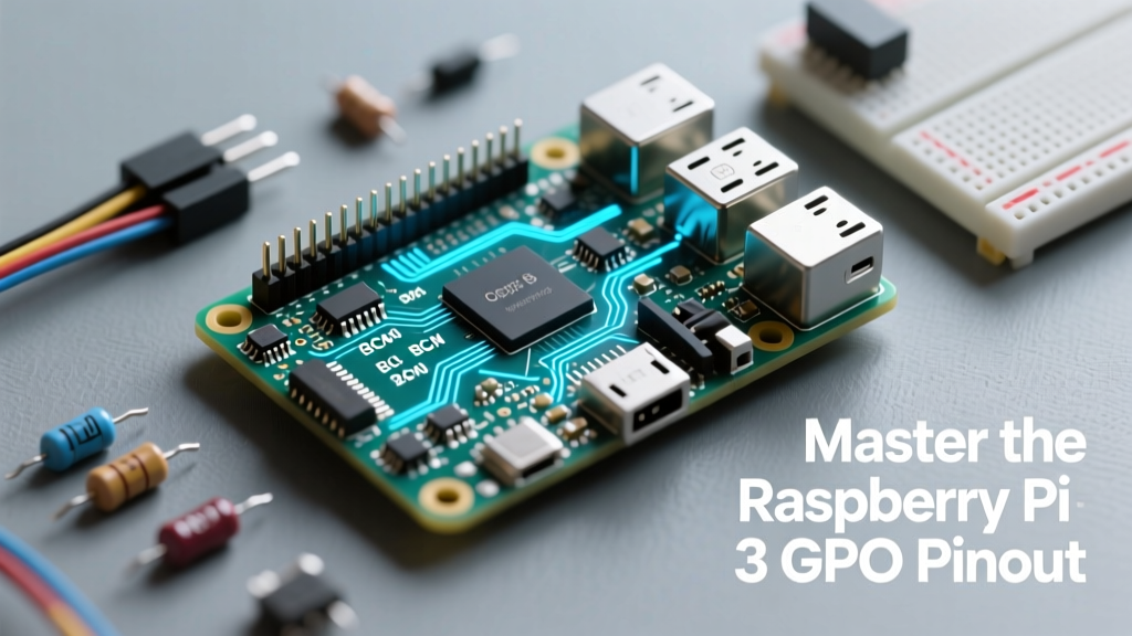
While microcontrollers like the ATmega328P dominate low-level hardware control, the Raspberry Pi 3 frequently serves as the master brain in complex maker ecosystems. Understanding the raspberry pi 3 gpio pinout is the foundational step for bridging high-level Linux processing with low-level sensor networks. The Pi 3 (both Model B and Model B+) features a 40-pin header, but unlike traditional MCUs, these pins are multiplexed, share power rails, and operate on strictly regulated logic levels.
When configuring your environment, you must choose between two primary numbering schemes: BOARD and BCM. The BOARD scheme refers to the physical pin numbers (1 through 40), which is intuitive for beginners using a ribbon cable or GPIO breakout board. However, the BCM (Broadcom SOC channel) scheme maps directly to the internal silicon routing of the BCM2837 chip. For any serious configuration, especially when writing Python scripts or C++ daemons, BCM is the industry standard. For instance, Physical Pin 3 corresponds to BCM 2, which is hardcoded as the I2C1 SDA line.
The Deprecation of WiringPi and Modern Alternatives
Historically, makers relied on the WiringPi library to map GPIO states using a custom 0-31 numbering system. As of 2026, WiringPi is fully deprecated and unsupported on modern 64-bit Raspberry Pi OS builds. Attempting to force legacy WiringPi installations often results in kernel panics or incorrect pin mapping on the Pi 3. Instead, configuration guides now universally recommend the GPIO Zero Documentation for Python, or direct memory-mapped register access via /dev/gpiomem for C/C++ applications.
Critical Voltage Tolerances and Hardware Failure Modes
The most common catastrophic failure in hybrid Pi-Arduino projects stems from a fundamental misunderstanding of logic levels. The Raspberry Pi 3 operates exclusively on 3.3V logic. The GPIO pins are not 5V tolerant. Feeding a 5V signal from an Arduino Uno or a standard 5V sensor directly into a Pi 3 GPIO pin will bypass the internal protection diodes, overvoltage the SoC, and permanently destroy the ARM core or the onboard 3.3V linear regulator.
Warning: Never backfeed 5V into the 3.3V power rail (Physical Pin 1). While the 5V pins (Physical Pins 2 and 4) can accept power from a bench supply, the 3.3V rail is an output from the internal switching regulator. Backfeeding 3.3V will fry the regulator.
Below is a structured breakdown of the voltage thresholds and safe operating parameters for the Pi 3 GPIO array:
| Parameter | Specification | Failure Threshold |
|---|---|---|
| Logic High (Input) | 1.35V to 3.3V | > 3.6V (Risk of SoC damage) |
| Logic Low (Input) | 0V to 1.0V | Negative voltage (No protection) |
| Max Source/Sink Current | 16mA per pin | > 20mA (Trace burnout risk) |
| Total GPIO Bank Current | 50mA aggregate | > 50mA (Thermal throttling/damage) |
| Internal Pull Resistors | ~50kΩ to 65kΩ | N/A (Configurable via software) |
Configuring Hardware Protocols via raspi-config
The raspberry pi 3 gpio pinout is highly flexible, but secondary functions like I2C, SPI, and UART are disabled by default to save memory and prevent boot conflicts. Configuring these requires interacting with the device tree overlays.
I2C Configuration (Pins 3 and 5)
The primary I2C bus (I2C1) is located on BCM 2 (SDA) and BCM 3 (SCL). These pins feature onboard 1.8kΩ pull-up resistors tied to the 3.3V rail, making them ideal for connecting sensors like the BME280 or MPU6050. To enable this bus, run sudo raspi-config, navigate to Interface Options, and enable I2C. For advanced users editing the config.txt documentation directly, ensure dtparam=i2c_arm=on is present.
UART and the Mini-UART Conflict (Pins 8 and 10)
Physical Pins 8 (TXD) and 10 (RXD) map to the serial console. On the Pi 3, the primary hardware UART (PL011) is routed to the Bluetooth module by default, leaving the less stable 'mini-UART' mapped to the GPIO header. This causes severe baud-rate drift when communicating with external microcontrollers. To fix this and route the stable PL011 UART to the GPIO header, you must add dtoverlay=disable-bt and enable_uart=1 to your /boot/firmware/config.txt file, then disable the serial console via raspi-config.
Bridging the Gap: Raspberry Pi 3 to Arduino Integration
Integrating the Pi 3 with 5V microcontrollers like the Arduino Mega or Nano requires bidirectional logic level shifting. While you can use a simple resistor voltage divider for unidirectional signals (e.g., reading a 5V sensor on a Pi input), bidirectional buses like I2C or SPI require active level shifters.
- Voltage Divider (TX only): Use a 2.2kΩ resistor connected to the 5V TX line, and a 3.3kΩ resistor connected to ground. The junction feeds the Pi 3 RX pin, safely dropping 5V down to approximately 3.0V.
- MOSFET Level Shifter (I2C/SPI): Utilize a BSS138 N-channel MOSFET breakout board. These boards use the pull-up resistors on both the high-voltage (5V) and low-voltage (3.3V) sides to safely translate logic states without frying the BCM2837 silicon.
- Optocouplers (Industrial): For environments with heavy EMI or inductive loads (like relays and motors), use an optocoupler like the PC817 to physically isolate the Pi 3 GPIO from the MCU control circuit.
Handling the Pi 3 Model B vs. Model B+ Power Variations
While the logical pinout remains identical across the Pi 3 Model B and Model B+, the physical power delivery capabilities differ. The Model B+ features an improved power regulation circuit and supports Power over Ethernet (PoE) via four additional pins near the USB ports. If you are designing a custom HAT (Hardware Attached on Top), ensure your PCB footprint accounts for the PoE header spacing if you intend to support the B+ variant. Furthermore, the Model B+ handles transient current spikes on the 5V rail slightly better, but the 3.3V rail limits remain strictly enforced across both revisions.
Software Abstraction: Safe Pin State Management
When writing configuration scripts, always implement safe state cleanup. If a Python script crashes while a GPIO pin is set to HIGH, the pin may remain HIGH on the next boot, potentially triggering connected relays or MOSFETs unexpectedly. Using the gpiozero library automatically handles cleanup when the script exits. For instance, initializing an LED with led = LED(17) ensures that pin BCM 17 is safely reverted to an input state upon script termination, preventing ghost voltages and protecting your connected hardware.
Mastering the raspberry pi 3 gpio pinout requires respecting the physical limitations of the Broadcom SoC while leveraging the immense software flexibility of Linux. By adhering to strict 3.3V logic boundaries, properly configuring device tree overlays for UART and SPI, and utilizing modern abstraction libraries, you can build robust, hybrid SBC-MCU architectures that survive long-term deployment. For definitive visual references during physical wiring, always keep a bookmark to Pinout.xyz on your workbench monitor.