
The Anatomy of a Serial.begin() Failure
When you call Serial.begin(9600) in your Arduino sketch, you are not merely toggling a software switch. You are instructing the microcontroller to configure hardware registers, allocate buffer memory, and initialize communication protocols. When this initialization fails, the symptoms range from silent boot hangs and garbled serial monitor output to complete upload failures. As of 2026, with the widespread adoption of the Arduino Uno R4 series alongside classic AVR boards, understanding the architectural differences between Hardware UART and USB-CDC is critical for effective troubleshooting.
This guide bypasses generic advice and dives deep into the register-level and architectural reasons why your serial initialization is failing, providing exact code fixes and hardware workarounds.
Diagnostic Matrix: Symptom to Root Cause
Use this matrix to quickly identify your specific failure mode before applying the detailed fixes below.
| Symptom | Root Cause | Affected Hardware | Primary Fix |
|---|---|---|---|
| Sketch hangs on boot, no LED blink | USB-CDC blocking wait loop | Leonardo, Micro, Uno R4, Nano 33 | Implement timeout wrapper |
| Upload fails (stk500_recv error) | External circuit on Pins 0/1 | Uno R3, Mega 2560, Nano (AVR) | Disconnect RX/TX during flash |
| Garbage characters in Serial Monitor | Baud rate clock drift / UBRR error | Clones with ceramic resonators | Drop to 38400 or 57600 baud |
| Serial stops working after 10 mins | Stack overflow corrupting USART registers | All 8-bit AVR boards | Audit memory usage, reduce local vars |
Fix 1: Resolving the USB-CDC Timeout Trap
A common mistake when migrating from an Arduino Uno R3 (ATmega328P) to a board with native USB like the Leonardo (ATmega32U4) or the modern Arduino Uno R4 Minima (Renesas RA4M1) is the misuse of the while(!Serial); blocking loop.
The Problem
On native USB boards, the serial connection is virtual (USB-CDC). If the board is powered by a wall adapter or battery without a PC attached, the !Serial condition remains true indefinitely. Your sketch will freeze at the setup phase, never reaching the main loop. This is a frequent culprit in standalone IoT deployments and battery-operated sensor nodes.
The Actionable Fix
Never use an infinite blocking loop in production firmware. Instead, implement a non-blocking timeout mechanism. This allows the microcontroller to wait for a serial connection for a maximum of 3 seconds before proceeding with autonomous operation.
void setup() {
  Serial.begin(115200);

  // Non-blocking timeout implementation
  unsigned long serialWaitStart = millis();
  while (!Serial && (millis() - serialWaitStart) < 3000) {
    // Yield to background USB-CDC tasks on R4/ARM boards
    delay(10);
  }

  if (Serial) {
    Serial.println('USB-CDC Connected.');
  } else {
    // Proceed with autonomous headless operation
  }
}
According to the Arduino Serial Reference, native USB ports do not physically assert a hardware line when connected, making software-side timeout management mandatory for robust field deployments.
Fix 2: Hardware UART Pin Conflicts (The Bootloader Handshake)
If you are using a classic AVR board like the Uno R3 or Mega 2560, Serial maps directly to Hardware UART0, which shares physical pins D0 (RX) and D1 (TX). These same pins are used by the ATmega16U2 USB-to-Serial bridge chip to communicate with the bootloader during sketch uploads.
Failure Mode: Upload Rejection
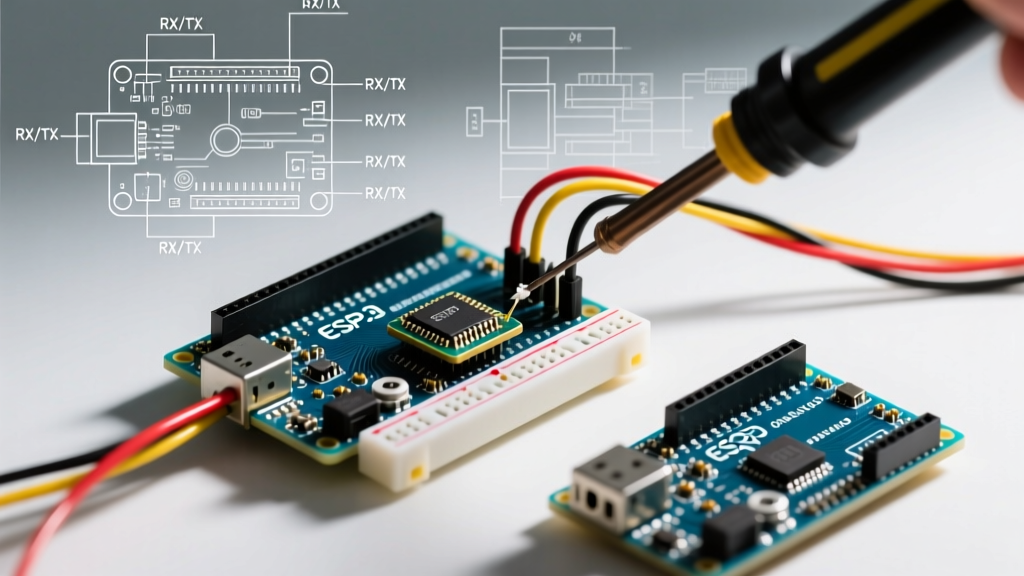
If you have external components wired to D0 and D1—such as a GPS module, an RS-485 transceiver, or even a simple LED with a low-value resistor—the external circuit can pull the RX/TX lines high or low. When the Arduino IDE attempts to upload a sketch, the bootloader initiates the STK500 protocol handshake at 115200 baud. If the external circuit clamps the voltage, the handshake fails, resulting in the dreaded avrdude: stk500_recv(): programmer is not responding error.
Hardware and Software Solutions
- The Hardware Rule: Never hard-solder components directly to Pins 0 and 1. Always use a jumper wire or a dip-switch so they can be physically disconnected during the upload phase.
- Use Software Serial or Alt UART: If you must communicate with a peripheral while keeping the main serial line free for debugging, use
SoftwareSerialon pins like D8 and D9 (limited to 57600 baud reliably), or useSerial1,Serial2, andSerial3if you are on an Arduino Mega 2560. - Series Resistors: If you absolutely must connect a sensor to D0/D1, place a 220Ω to 470Ω resistor in series with the RX line. This limits the current the external device can sink/source, allowing the 16U2 bridge chip to overpower the sensor during the brief upload window.
Fix 3: Baud Rate Math and Clock Drift Anomalies
Garbage characters (e.g., ÿÿÿ or random wingdings) in the Serial Monitor usually indicate a baud rate mismatch. However, if both your code and Serial Monitor are set to 115200, the issue is likely hardware clock drift.
The AVR UBRR Calculation Problem
On 8-bit AVR microcontrollers like the Microchip ATmega328P, the baud rate is generated by dividing the system clock (usually 16MHz) using the USART Baud Rate Register (UBRR). The formula is:
UBRR = (F_CPU / (16 * Baud)) - 1
For a 16MHz clock at 115200 baud, the math yields 7.68. Because the UBRR must be an integer, the compiler truncates or rounds it to 8. If UBRR is set to 8, the actual baud rate generated by the hardware becomes 111,111 baud. This results in a -3.55% error. While some PC USB-UART chips can tolerate this, others will flag framing errors and drop packets, especially over long cable runs.
The Fix for Clone Boards
Cheap Arduino clones often use low-tolerance ceramic resonators instead of precision quartz crystals, compounding this mathematical error with physical temperature drift. If you experience intermittent serial corruption at 115200 baud on a clone board:
- Drop your baud rate to 38400 or 57600. These rates divide evenly into 16MHz with near-zero percent error (UBRR = 25 and 16, respectively).
- Enable the U2X (Double Speed) bit in the USART control register if you are writing bare-metal code, which changes the divisor from 16 to 8, cutting the baud rate error in half.
Advanced Edge Case: Stack Collision Corrupting Serial
If your serial communication works perfectly for the first few minutes and then abruptly stops outputting data or causes the MCU to reboot, you are likely experiencing a stack overflow. On the ATmega328P, SRAM is limited to 2KB. The stack grows downward from the top of RAM, while global variables and the Serial TX/RX buffers (typically 64 bytes each) grow upward from the bottom.
If you use deep recursive functions or allocate large local arrays inside your loop(), the stack pointer will collide with the Serial buffer memory space. This silently overwrites the hardware USART configuration registers or the buffer pointers, killing serial output without triggering a hard fault.
How to Audit and Fix
Use the FreeMemory() function or the avr-size toolchain command to check your static RAM footprint. If your globals and buffers exceed 1.5KB, you must optimize:
- Move constant strings to Flash memory using the
F()macro:Serial.println(F('Sensor initialized')); - Reduce the default Serial buffer size by modifying
HardwareSerial.hin the Arduino core if you only need to transmit short telemetry bursts. - Avoid
Stringobjects entirely; use fixed-sizechararrays andsnprintf()to prevent heap fragmentation.
Summary Checklist for Field Deployments
Before deploying an Arduino-based node in a remote environment, verify the following:
- USB-CDC blocking loops have been replaced with timeout wrappers.
- Pins 0 and 1 are physically isolated from external loads during firmware updates.
- Baud rates are chosen based on mathematical divisibility of the MCU clock, not just arbitrary high speeds.
- SRAM headroom is verified to prevent stack-to-buffer collisions during extended uptime.
By treating Serial.begin() not as a simple macro but as a critical hardware initialization sequence, you eliminate the most common points of failure in microcontroller prototyping and production.