
The Hidden Cost of GPIO Friction in Embedded Workflows
When building embedded systems, the physical interface between your software and the real world is the Raspberry Pi GPIO header. For many makers, students, and professional engineers, this 40-pin array is a source of constant friction. Context-switching between IDEs, browser tabs for pinout diagrams, and messy breadboard wiring destroys momentum and introduces critical hardware risks. Optimizing how you interact with the Raspberry Pi GPIO header is not just about neat cables; it is about reducing cognitive load, preventing silicon damage, and accelerating the path from prototype to production.
With the introduction of the Raspberry Pi 5 and its RP1 southbridge chip, the underlying silicon architecture handling the pins has evolved, even though the physical 40-pin footprint remains backward compatible. This guide details a comprehensive workflow optimization strategy for hardware interfacing, software abstraction, and production scaling.
Physical Workspace and Pinout Memorization
The most common workflow bottleneck occurs when a developer needs to verify which physical pin corresponds to which BCM (Broadcom) GPIO number. Relying on web browsers to check Pinout.xyz mid-coding breaks concentration.
The Terminal-First Pinout Strategy
If you are using the gpiozero Python library, you already have a built-in pinout reference. By simply typing pinout in your Raspberry Pi terminal, the system prints a color-coded, ASCII-art diagram of the Raspberry Pi GPIO header directly to your console. This eliminates the need for alt-tabbing to a browser and keeps your hands on the keyboard. For headless setups via SSH, this terminal command is an absolute necessity for maintaining a rapid iteration loop.
Implementing a Strict Color-Coding Protocol
Hardware debugging consumes hours when wiring is ambiguous. Standardize your silicone jumper wire colors to match electrical potential and signal types. A professional workflow dictates:
- Red: 5V Power (Pin 2 or 4)
- Orange: 3.3V Power (Pin 1 or 17)
- Black: Ground (Any GND pin)
- Yellow: Digital I/O Signals
- Blue: I2C / SPI / UART Data Lines
Expert Insight: Never use red for 3.3V logic. Accidentally plugging a 5V sensor into a 3.3V BCM pin will instantly destroy the SoC on a Pi 4, or the RP1 chip on a Pi 5. Color discipline is your first line of defense.
Hardware Interfacing: Eliminating Connection Bottlenecks
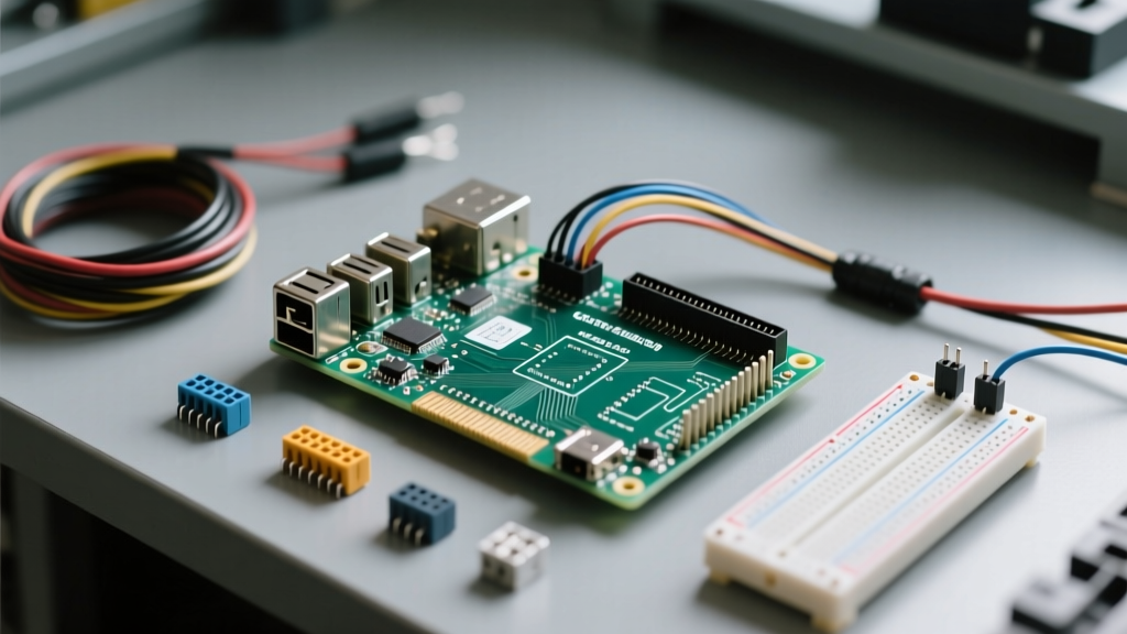
Directly plugging jumper wires into the Raspberry Pi GPIO header is fragile and unsuitable for anything beyond a 10-minute test. To optimize your build workflow, you must select the right breakout method for your project's maturity stage.
Prototyping Methods Comparison
| Breakout Method | Setup Time | Reliability | Best Workflow Stage |
|---|---|---|---|
| Direct Breadboard | 1 Minute | Low (Prone to loose connections) | Initial sensor validation |
| Ribbon Cable Breakout | 5 Minutes | Medium (Strain relief issues) | Complex multi-sensor breadboarding |
| Terminal Block HAT | 15 Minutes | High (Screw terminals lock wires) | Field testing and permanent installs |
| Custom Soldered HAT | Days | Maximum (Production ready) | Final product deployment |
Logic Level Shifting: A Mandatory Workflow Step
The Raspberry Pi operates strictly at 3.3V logic. Interfacing with 5V components (like standard Arduino modules, WS2812B LED strips, or legacy UART devices) requires voltage translation. Integrating a bidirectional logic level shifter (such as the BSS138-based Adafruit 4-channel shifter or the TXS0108E) into your standard workflow template prevents catastrophic hardware failure. Always route 5V sensor data through a shifter before it touches the Raspberry Pi GPIO header.
Software Abstraction for Rapid Iteration
Writing low-level register code or dealing with deprecated libraries slows down development. The official gpiozero library provides an object-oriented abstraction layer that dramatically speeds up the software side of your hardware workflow.
Why gpiozero Beats Legacy Libraries
Unlike the older RPi.GPIO library, which requires manual setup, teardown, and pin state management, gpiozero handles background threading and cleanup automatically. Consider the workflow difference when blinking an LED on BCM pin 17:
Legacy Workflow: Requires importing the library, setting warnings, defining pin modes, writing a try/except block for cleanup, and managing sleep timers.
Optimized gpiozero Workflow:
from gpiozero import LED
from time import sleep

led = LED(17)

while True:
    led.toggle()
    sleep(1)
This reduction in boilerplate code allows developers to focus on the core application logic rather than the intricacies of the Raspberry Pi GPIO header's software bindings.
Scaling Up: From Breadboard to HAT Production
Once your prototype is validated, the final workflow optimization is transitioning from messy jumper wires to a custom Hardware Attached on Top (HAT) PCB. Designing a HAT requires strict adherence to the mechanical and electrical specifications of the Raspberry Pi GPIO header.
Leveraging the EEPROM and I2C ID Pins
Pins 27 (ID_SD) and 28 (ID_SC) on the header are reserved exclusively for an EEPROM chip. In a professional workflow, you should design your custom PCB to include an I2C EEPROM. When the Raspberry Pi boots, it reads this EEPROM to automatically configure the GPIO pin states, load necessary device tree overlays, and identify the board. This auto-configuration eliminates the need for end-users to manually edit the config.txt file, resulting in a seamless, plug-and-play deployment experience.
Furthermore, utilizing the official Raspberry Pi hardware documentation ensures your mounting holes align perfectly with the M2.5 standoffs, preventing mechanical stress on the header solder joints. By treating the Raspberry Pi GPIO header not just as a row of pins, but as a structured system of power, logic, and identification, you transform your maker workflow from a chaotic trial-and-error process into a streamlined, professional engineering pipeline.