
Optimizing the Arduino Alarm System Workflow
Building an arduino alarm system is a classic rite of passage for makers, but scaling a project from a breadboard prototype to a reliable, multi-zone security node requires a disciplined engineering workflow. In 2026, with the proliferation of low-cost mmWave sensors and highly capable microcontrollers, the bottleneck in security projects is rarely the hardware itself. Instead, it is the system architecture, wiring methodology, and software state management that dictate success or failure.
A disorganized workflow leads to spaghetti code, intermittent hardware faults, and endless debugging sessions. By adopting a structured, modular approach to your Arduino alarm system, you can reduce build times by up to 40%, eliminate blocking-code vulnerabilities, and ensure your deployment survives real-world environmental stressors. This guide breaks down the optimal workflow for designing, coding, and deploying robust MCU-based security systems.
Phase 1: Component Selection and the 'Fail-Fast' Prototyping Stage
The first step in workflow optimization is selecting components that minimize integration friction. Historically, makers relied on the HC-SR501 PIR sensor for motion detection. However, PIR sensors are notorious for thermal drift, causing false alarms when sunlight hits a wall or when HVAC systems cycle on.
To optimize your workflow and eliminate weeks of troubleshooting false positives, transition to 24GHz mmWave radar modules like the HLK-LD2410. Priced around $3.50, the LD2410 provides static presence detection, adjustable gating zones, and immunity to thermal and lighting changes.
Sensor Technology Comparison Matrix
| Sensor Model | Technology | Avg. Cost (2026) | False Trigger Rate | Static Presence | Workflow Impact |
|---|---|---|---|---|---|
| HC-SR501 | Passive Infrared (PIR) | $1.50 | High (Thermal/Light) | No | Negative (Requires heavy software filtering) |
| RCWL-0516 | Microwave Doppler | $2.00 | Medium (Wall Penetration) | No | Neutral (Requires physical shielding) |
| HLK-LD2410 | 24GHz mmWave Radar | $3.50 | Very Low | Yes | Positive (Configurable via UART, highly reliable) |
For the microcontroller, bypass the legacy 5V Arduino Uno. The ESP32-C3 SuperMini (approx. $4.00) offers a 32-bit RISC-V architecture, native Wi-Fi/BLE for remote alerting, and deep sleep capabilities crucial for battery-backed alarm nodes. Because it operates at 3.3V, you must integrate a bi-directional logic level shifter (like the BSS138, ~$0.50) if you are interfacing with legacy 5V sirens or keypads.
Phase 2: Software Architecture and Eradicating Blocking Code
The single greatest workflow killer in MCU programming is blocking code. If your alarm system uses delay() to manage siren durations or exit timers, the system becomes blind to keypad inputs or secondary sensor triggers during that delay window. This creates a fragile system that fails under edge-case conditions.
Implementing a Finite State Machine (FSM)
Optimize your software workflow by abandoning linear scripting in favor of a Finite State Machine. An FSM explicitly defines every operational mode of your arduino alarm system. Define your states in an enum:
STATE_DISARMED: System idle, keypad active.STATE_EXIT_DELAY: Countdown active, motion ignored.STATE_ARMED: Sensors active, monitoring for breaches.STATE_ENTRY_DELAY: Breach detected, countdown to siren.STATE_TRIGGERED: Siren active, Wi-Fi alerts dispatched.
Use non-blocking timing via the millis() function to track state transitions. By capturing the timestamp when a state begins and comparing it against the current millis() value on every loop iteration, your MCU remains 100% responsive to button presses and serial commands, even while a 30-second exit delay is counting down.
Pro-Tip for Complex Nodes: If your alarm system requires concurrent tasks (e.g., polling an RFID reader while simultaneously maintaining a WebSocket connection to a home automation server), consider adopting FreeRTOS. Running discrete tasks on separate cores (using an ESP32) isolates network latency from critical sensor polling, ensuring a physical breach is never missed due to a Wi-Fi handshake delay.
Phase 3: Modular Wiring and Harness Standardization
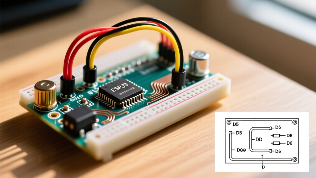
Spaghetti wiring on a breadboard is the root cause of 80% of field failures in DIY security systems. Oxidation, loose jumper wires, and accidental shorts will cause phantom alarms that are nearly impossible to debug. To optimize your physical build workflow, standardize your wiring harnesses before you ever pick up a soldering iron.
The JST-XH Connector Standard
Adopt JST-XH 2.54mm pitch connectors for all sensor and peripheral connections. While crimping JST connectors adds roughly two hours to your initial build time, it saves tens of hours in future maintenance. If a door contact sensor fails, you can simply unplug the JST connector and swap the module without desoldering a single wire.
Follow a strict color-code standard across your entire deployment to eliminate cognitive load during troubleshooting:
- Red: VCC (3.3V or 5V)
- Black: Ground (GND)
- Yellow: Digital Signal / GPIO
- Blue: I2C SDA / UART TX
- Green: I2C SCL / UART RX
For wire selection, use 26 AWG stranded silicone wire. As detailed in professional wiring guides like those from SparkFun, silicone insulation withstands high soldering temperatures without melting back, and the high strand count ensures flexibility, preventing work-hardening and wire breaks when routing cables through door frames or wall cavities.
Phase 4: Edge-Case Simulation and Automated Testing
Testing an alarm system by physically walking in front of sensors or opening doors 100 times is an inefficient use of your time. Optimize your QA workflow by building a Hardware-in-the-Loop (HIL) test routine.
Serial Command Injection
Program a hidden serial command interface into your FSM. By sending specific strings over the USB serial monitor (e.g., !SIM_BREACH_ZONE1), you can force the system into the STATE_TRIGGERED phase instantly. This allows you to verify that your Wi-Fi alert payloads, siren relays, and logging functions work correctly without leaving your workbench.
Click to Expand: Top 3 Field Failure Modes & Mitigations
- Power Supply Brownouts: When a 12V piezo siren activates, it can draw 500mA+, causing a voltage drop that resets the Arduino. Mitigation: Isolate the siren on a separate 12V rail and use an optocoupler (like the PC817) to trigger the relay, keeping the high-current inductive spike entirely off the MCU's 5V/3.3V logic plane.
- Reed Switch Bounce: Magnetic door contacts suffer from mechanical bounce, registering a single door opening as 15 rapid open/close events, flooding your logs. Mitigation: Implement a 50ms software debounce timer in your FSM before registering a state change.
- Wi-Fi Reconnection Loops: If the router reboots, the ESP32 may hang in a connection loop, ignoring sensors. Mitigation: Implement a hardware watchdog timer (WDT) that forces a hard reset if the network task fails to check in within 60 seconds.
Conclusion
Transitioning from a hobbyist mindset to an engineering workflow transforms your arduino alarm system from a fragile experiment into a dependable security asset. By selecting modern mmWave sensors, enforcing non-blocking FSM software architectures, standardizing JST wiring harnesses, and utilizing serial-injection testing, you drastically reduce both development time and long-term maintenance headaches. Apply these optimization strategies to your next build, and you will deploy a system that is as robust as it is intelligent.