
The Hidden Cost of the Default Blink Sketch
Every maker's journey begins with the default Blink.ino sketch. While it serves as a functional hardware verification tool, relying on its underlying logic for production firmware is a critical workflow error. When professionals approach arduino coding for led blinking, they immediately discard the introductory delay() paradigm in favor of event-driven, non-blocking architectures.
To understand why, we must examine the ATmega328P microcontroller at the heart of the classic Arduino Uno R3. Running at a 16 MHz clock speed, the CPU executes roughly 16 million instructions per second. When you invoke delay(1000), you are not merely pausing the LED; you are forcing the CPU into a tight, wasteful loop that consumes 16 billion clock cycles. During this time, the microcontroller cannot read sensors, process serial data, or manage wireless communication stacks. According to the AVR Libc delay documentation, these blocking functions halt the main thread entirely, rendering multitasking impossible.
Non-Blocking Workflows: Mastering the millis() Rollover
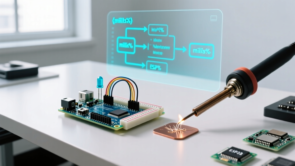
The first step in optimizing your workflow is transitioning to time-tracking via the millis() function. This approach allows the main loop() to execute thousands of times per second, checking if a specific time interval has elapsed before toggling the GPIO pin.
Critical Edge Case Warning: The
millis()counter is stored in an unsigned 32-bit integer. After approximately 49.7 days (4,294,967,295 milliseconds), the counter overflows and resets to zero. If your logic uses addition (e.g.,currentMillis >= previousMillis + interval), your code will fail catastrophically at the rollover boundary. Always use subtraction:currentMillis - previousMillis >= interval. The unsigned math naturally resolves the rollover without throwing negative values.
Implementing this subtraction method is a hallmark of professional firmware development. As detailed in the official Arduino millis() reference, this non-blocking pattern frees up the CPU to handle I2C sensor polling or UART interrupts concurrently with the LED state management.
Hardware Timer Offloading: The Ultimate Optimization
While millis() frees the main loop, it still requires the CPU to wake up, read the system timer, perform subtraction, and evaluate a boolean condition on every single loop iteration. For ultra-optimized workflows, we offload LED blinking entirely to dedicated hardware peripherals.
The ESP32 LEDC Peripheral
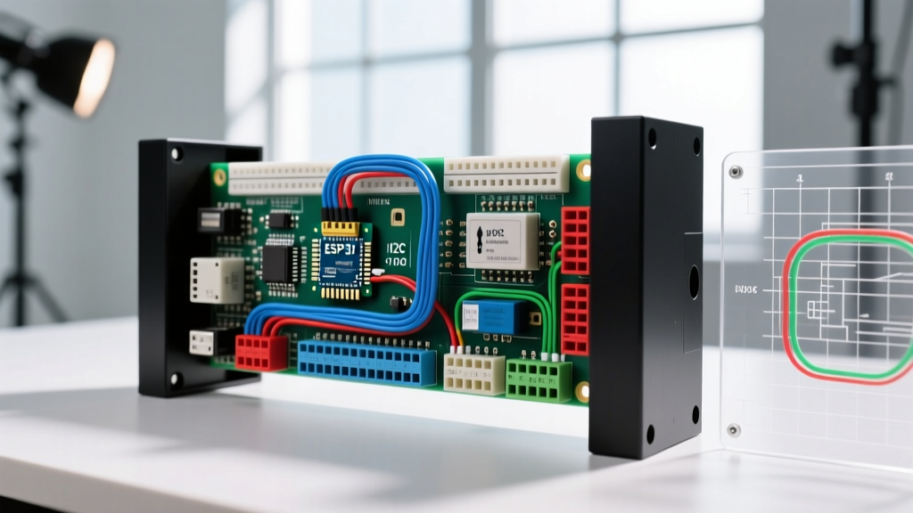
If your project utilizes an ESP32-WROOM-32 module (commonly found on $4.50 - $6.00 development boards in 2026), you have access to the LED Control (LEDC) peripheral. The LEDC hardware timer can generate PWM signals and handle software-defined blinking patterns without any CPU intervention. By configuring the LEDC fade and duty cycle registers, the hardware toggles the GPIO pin autonomously. The Espressif LEDC API documentation provides exhaustive register maps for configuring these hardware timers, allowing your main application code to remain completely untouched by timing logic.
AVR Timer1 Interrupts
For legacy 8-bit AVR boards, you can configure Timer1 to trigger an Interrupt Service Routine (ISR) at precise intervals. By setting the Output Compare Register (OCR1A) and enabling the compare match interrupt, the hardware automatically pauses the main program, executes a 3-line ISR to toggle the PORTB register, and resumes. This reduces CPU overhead from continuous polling to near-zero.
Object-Oriented State Machines for Multi-LED Arrays
When scaling from a single indicator LED to a complex user interface featuring multiple status lights (e.g., Wi-Fi connection, sensor calibration, battery low), procedural code quickly devolves into spaghetti. Optimized workflow demands an Object-Oriented Programming (OOP) approach using C++ classes.
By encapsulating LED behavior into a Blinker class, you create reusable state machines. Each object instance stores its own previousMillis, interval, and pinState in the microcontroller's SRAM.
- Memory Footprint Awareness: On an ATmega328P with only 2,048 bytes of SRAM, memory management is critical. A standard OOP object containing a pin number (1 byte), state (1 byte), and timing variables (8 bytes) consumes roughly 10 bytes per LED. Instantiating 20 LEDs consumes 200 bytes—well within safe limits, leaving ample headroom for serial buffers and sensor arrays.
- Pattern Abstraction: Advanced classes can accept arrays of timing intervals to create complex patterns (e.g., SOS morse code, heartbeat pulses) without blocking the main thread.
- Hardware Integration: For projects requiring 50+ LEDs, OOP wrappers can be designed to interface directly with TLC5940 constant-current sink drivers or 74HC595 shift registers, abstracting the SPI/I2C bit-banging away from the business logic.
Power Profiling: Sleep Modes vs. Active Blinking
Workflow optimization is incomplete without addressing power consumption, especially for battery-operated IoT nodes. A standard 5mm red LED draws roughly 20mA. Combined with an active ATmega328P drawing 15mA, a continuously blinking node will drain a 2000mAh 18650 lithium cell in less than three days.
Professional engineers optimize this by utilizing the microcontroller's hardware sleep modes. Instead of using delay() or millis() to wait for the next blink state, the firmware configures the Watchdog Timer (WDT) or an external Real-Time Clock (RTC) interrupt, puts the MCU into SLEEP_MODE_PWR_DOWN, and shuts off the ADC and brown-out detector. In this state, the MCU draws mere nanoamps. The RTC wakes the chip every 5 seconds, toggles a high-efficiency Kingbright L-7104 series LED (which achieves high luminosity at just 2mA), and immediately returns to sleep. This workflow extends battery life from days to several months.
Workflow Comparison Matrix
Selecting the correct architecture depends on your specific hardware constraints and project scale. Use the matrix below to guide your development workflow:
| Method | CPU Overhead | Scalability | Power Efficiency | Best Use Case |
|---|---|---|---|---|
delay() |
100% (Blocking) | Very Poor | Poor (Active) | Initial hardware smoke-tests only. |
millis() Polling |
Low (Continuous polling) | Good (up to 10 LEDs) | Moderate | Standard sensor nodes with concurrent I/O. |
| Hardware Timers (ISR) | Near Zero | Excellent | High | Precise timing, audio synthesis, motor control. |
| LEDC / PWM Peripherals | Zero (Autonomous) | Excellent | High | ESP32 IoT dashboards, complex UI indicators. |
| WDT / RTC Sleep Wake | Zero (Sleeping) | Moderate | Maximum (Nanoamps) | Remote environmental sensors, off-grid telemetry. |
Conclusion: Elevating Your Firmware Standards
Mastering arduino coding for led blinking is not about making an LED flash; it is about establishing a robust, non-blocking foundation for your entire firmware architecture. By abandoning blocking delays, leveraging hardware-specific peripherals like the ESP32 LEDC, and structuring your code via object-oriented state machines, you transform fragile hobbyist scripts into resilient, production-grade embedded systems. Always profile your power states, respect the 32-bit rollover boundaries, and let the hardware timers do the heavy lifting.