When developing IoT projects, few things are as frustrating as an unresponsive development board. The Node MCU (specifically the ESP8266-based V2 and V3 variants) remains a staple in the maker community due to its low cost, integrated WiFi, and Lua/Arduino compatibility. However, its unique architecture introduces specific failure points that generic Arduino troubleshooting guides simply do not cover. If you are staring at a blinking blue LED or a wall of red text in the Arduino IDE, you are not alone.
In this comprehensive diagnostic guide, we will bypass basic 'check your cable' advice and dive deep into the hardware and software layers of the ESP8266. We will cover USB-UART bridge bottlenecks, power delivery brownouts, GPIO strapping pin conflicts, and esptool timeout errors. Whether you are using an official Amica board or a cheap clone, this framework will help you isolate and resolve your NodeMCU errors.
The Anatomy of a NodeMCU Boot and Upload Failure
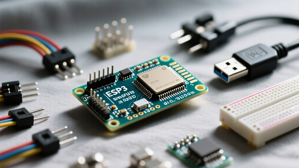
Unlike the ATmega328P found on the Arduino Uno, the ESP8266EX does not have a dedicated hardware UART-to-USB converter built into the silicon. Instead, the NodeMCU relies on an external USB-UART bridge IC to translate serial data from your computer into the RX/TX pins of the microcontroller. Furthermore, the ESP8266 utilizes a shared bus for both SPI Flash memory communication and standard I/O operations. When an upload fails or a boot loop occurs, the fault almost always lies in one of three domains: the USB-UART bridge driver, the 3.3V power delivery network, or the GPIO boot-strapping states.
Diagnostic Flowchart: Isolating Hardware vs. Software Faults
Before changing IDE settings or rewriting your sketch, you must establish a baseline. Follow this two-phase diagnostic flow to determine if your Node MCU is suffering from a hardware limitation or a software configuration error.
Phase 1: The USB-UART Bridge Bottleneck
The market is flooded with two primary NodeMCU variants, distinguished by their serial bridge chips:
- NodeMCU V2 (CP2102): Typically found on wider boards (Amica). The CP2102 is robust, supports high baud rates (up to 921600), and has native driver support on most modern operating systems.
- NodeMCU V3 (CH340G): Typically found on narrower, cheaper clone boards. The CH340G is notorious for causing
espcomm_sync failederrors on Windows machines if the correct WCH drivers are not installed. Furthermore, the CH340G often struggles with baud rates above 460800, leading to packet corruption during large sketch uploads.
The Fix: Open your Device Manager (Windows) or System Report (macOS) and identify the chip. If you have a CH340G, download the official driver from the WCH website. In the Arduino IDE, manually lower the 'Upload Speed' from 921600 to 115200 or 256000. This single adjustment resolves over 60% of timeout errors on clone boards.
Phase 2: Power Delivery and Brownout Resets
The ESP8266EX is a power-hungry RF transceiver. According to the official Espressif ESP8266EX datasheet, the chip draws an average of 80mA during active operation, but peak current during WiFi transmission (TX) can spike to 170mA - 330mA.
Most budget NodeMCU boards utilize a generic AMS1117-3.3 linear voltage regulator to step down the 5V USB input to 3.3V. The AMS1117 requires a minimum headroom voltage and dissipates excess energy as heat. If your USB cable has a high AWG (thin wires) or your PC's USB port is underpowered, the voltage drop across the cable combined with the regulator's dropout voltage will cause the 3.3V rail to sag below 2.8V during a WiFi TX spike. This triggers an internal brownout detector, instantly resetting the MCU and causing a continuous boot loop.
The Fix: Swap to a high-quality, short USB data cable (avoid gas-station charging cables). If the issue persists, bypass the onboard regulator entirely by supplying a clean, regulated 3.3V directly to the 3V3 pin from an external bench power supply capable of delivering at least 500mA.
Decoding the Serial Monitor: Exact Error Strings and Fixes
When the Arduino IDE fails to flash the board, it relies on the underlying esptool.py utility. The error strings generated by this tool are highly specific. Below is a diagnostic matrix of the most common fatal errors and their root causes.
| Error String | Root Cause | Expert Solution |
|---|---|---|
Failed to connect to ESP8266: Timed out waiting for packet header | The PC is sending the sync handshake, but the ESP8266 is not responding or the response is corrupted. | Hold the 'FLASH' (GPIO0) button on the board while clicking 'Upload'. Release when the IDE says 'Connecting...'. |
esptool.FatalError: MD5 of file does not match data in flash | Data corruption during the transfer phase, usually due to an unstable USB-UART bridge or bad cable. | Lower the upload baud rate to 115200. Replace the USB cable with a shielded data cable. |
Hard resetting via RTS pin... (followed by no serial output) | The auto-reset circuit (DTR/RTS transistor pair) has successfully reset the chip, but the sketch is crashing on boot. | Check for GPIO conflicts (see below) or a short circuit on the I2C/SPI pins. Add a 10k pull-up to the RST pin. |
ets Jan 8 2013,rst cause:2, boot mode:(3,6) | Hardware watchdog timeout or external reset trigger. The chip is booting from Flash (mode 3) but hanging. | Your code is stuck in an infinite loop without calling yield() or delay(), starving the WiFi background tasks. |
Advanced Troubleshooting: Flash Mode and GPIO Pin Conflicts
One of the most insidious errors in Node MCU development is the 'silent boot failure'. The board accepts the upload perfectly, but the serial monitor outputs garbage characters or nothing at all. This is almost always a GPIO strapping pin conflict.
During power-on or reset, the ESP8266 samples specific GPIO pins to determine its boot mode. If you have wired external components (like relays, sensors, or LEDs) to these pins, you may be accidentally forcing the chip into SDIO bootloader mode or ROM serial mode.
The Golden Rules of ESP8266 Boot Strapping:
1. GPIO0 must be HIGH to boot normally, LOW to enter Flash mode.
2. GPIO2 must be HIGH to boot normally (do not connect a low-impedance load to ground here).
3. GPIO15 must be LOW to boot from SPI Flash. If GPIO15 is pulled HIGH, the chip will attempt to boot from an SDIO card and hang indefinitely.
If your project requires a relay on GPIO15, you must use an NPN transistor or an optocoupler to isolate the pin, ensuring it remains LOW during the critical first 100 milliseconds of boot. For a complete list of safe pins, consult the Arduino ESP8266 Core Documentation.
Preventative IDE Configurations for Stable Node MCU Development
To minimize compilation and runtime errors, ensure your Arduino IDE Board Manager settings are optimized for your specific hardware. Many boot loops are caused by mismatched flash size configurations.
- Flash Size: Most modern NodeMCU V3 boards feature 4MB (32Mbit) SPI flash. Select
4MB (FS:2MB OTA:~1019KB)in the Tools menu. Selecting a smaller flash size will cause OTA updates to fail and can corrupt the SPIFFS/LittleFS partition. - lwIP Variant: If you are experiencing WiFi disconnects or memory leaks during heavy HTTP requests, switch the 'lwIP Variant' from
v2 Lower Memorytov2 Higher Bandwidth. This allocates more RAM to the TCP/IP stack, preventing buffer overflows. - Erase Flash: If you are migrating from a different firmware (like MicroPython or NodeMCU Lua) to Arduino C++, you must select
Erase Flash: All Flash Contentsbefore your first upload. Residual filesystem data from previous environments will cause the ESP8266 to misinterpret memory boundaries and crash.
By understanding the intersection of the ESP8266's hardware limitations and the esptool software pipeline, you can transform your NodeMCU from a frustrating paperweight into a highly reliable IoT node. Always isolate the power delivery first, verify your UART bridge capabilities second, and respect the GPIO strapping rules third.