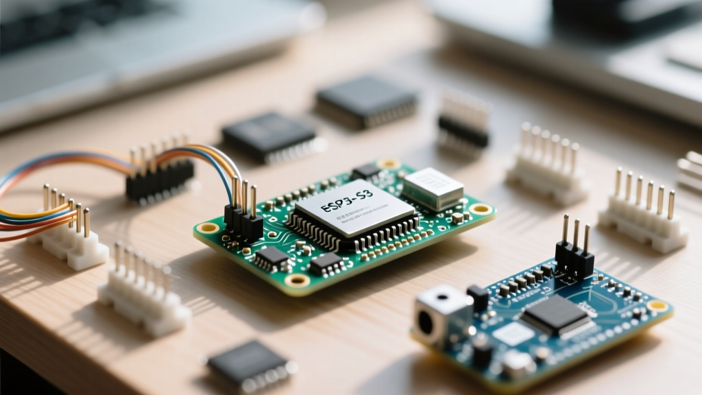

The Architecture Shift: Why Classic Code Fails on Newer ESP32s
Upgrading from the classic ESP32-WROOM-32 to the newer ESP32-S series (commonly referred to by makers as modern ESP32s) is a rite of passage for advanced IoT developers. While the ESP32-S2 and ESP32-S3 offer massive improvements in AI processing, native USB OTG, and enhanced security, they are not drop-in replacements. Legacy Arduino sketches that compile flawlessly on the original dual-core Xtensa LX6 will often crash, fail to flash, or throw Guru Meditation Errors on the newer Xtensa LX7 architecture.
The original ESP32 relies on a specific matrix of GPIO routing and peripheral defaults that Espressif completely overhauled for the S-series. The ESP32-S3, for instance, introduces vector instructions for AI acceleration and a completely redesigned I/O multiplexer. When you attempt to compile a legacy sketch using the Arduino IDE, the ESP32 Core translates your high-level C++ calls into hardware-specific register operations. If your code relies on implicit default pins for hardware I2C or assumes the presence of a secondary UART bridge, the compiler might succeed, but the runtime execution will fail silently or crash. Furthermore, the memory map for the SPI flash and PSRAM has been reorganized to support Octal SPI (OPI) interfaces, meaning legacy memory allocation pointers can trigger immediate cache panics.
Step 1: Resolving Pinout and Strapping Pin Conflicts
One of the most critical hardware differences lies in the strapping pins. These pins dictate the boot mode, flash voltage, and log output during the bootloader phase. If you are migrating a custom PCB design from the classic ESP32 to an ESP32-S3-WROOM-1 module, you must re-evaluate your pull-up and pull-down resistor networks.
| Feature | Classic ESP32 (WROOM-32) | ESP32-S3 (WROOM-1) | Migration Action Required |
|---|---|---|---|
| Bluetooth | Classic + BLE 4.2 | BLE 5.0 Only | Rewrite BluetoothSerial to NimBLE |
| USB Interface | UART via CP2102/CH340 | Native USB OTG + JTAG | Enable CDC in IDE, remove bridge |
| PSRAM | QSPI (Max 4MB) | OPI (Up to 8MB+) | Update IDE to Octal mode |
| Strapping Pins | GPIO0, 2, 4, 5, 12, 15 | GPIO0, 3, 45, 46 | Reassign GPIO12/15 in custom PCBs |
As shown in the table, GPIO12 and GPIO15 are no longer strapping pins on the S3. Instead, GPIO3, GPIO45, and GPIO46 take precedence. If your legacy PCB pulls GPIO45 high during boot, the S3 will enter an unintended boot mode, preventing your sketch from executing. Always consult the official Espressif ESP32-S3 Hardware Reference before finalizing any schematic migrations.
Step 2: Adapting to Native USB and UART Bridge Differences
Classic ESP32 development boards utilize external UART-to-USB bridge chips like the CP2102 or CH340. Modern ESP32s, specifically the S2 and S3, feature native USB OTG (On-The-Go) and built-in USB Serial/JTAG controllers. This eliminates the need for external bridge chips but fundamentally changes how the Arduino IDE communicates with the board.
To migrate your sketch, you must enable the native CDC (Communication Device Class) in the Arduino IDE. Navigate to Tools > USB CDC On Boot and select Enabled. If you fail to do this, your Serial.print() debugging statements will output to the non-existent default UART pins, and you will see no data in the Serial Monitor.
Flashing the board also requires a new physical sequence. Because there is no external DTR/RTS auto-reset circuit on native USB-only boards, you must manually force the bootloader stub. To flash a stubborn S3 board: press and hold the BOOT button (GPIO0), tap the RESET button, and then release the BOOT button. The Arduino ESP32 Core GitHub repository contains detailed schematics on how to implement auto-reset circuits using discrete transistors if you are designing a custom carrier board.
Step 3: The Bluetooth Classic Trap and NimBLE Migration
This is where 90% of legacy migrations fail. The original ESP32 supports both Bluetooth Classic (BR/EDR) and Bluetooth Low Energy (BLE). Many legacy sketches use the ubiquitous BluetoothSerial.h library to create virtual serial ports over classic Bluetooth. The ESP32-S3 does not have a Bluetooth Classic radio; it only supports BLE 5.0.
If your sketch includes BluetoothSerial.h, it will either fail to compile or crash at runtime on an S3. You must rewrite your wireless stack using the NimBLE library, which is now the standard for BLE on the ESP32 Arduino Core. NimBLE is significantly more memory-efficient and supports the BLE 5.0 long-range and high-throughput features.
// Legacy Classic Bluetooth (Fails on S3)
#include <BluetoothSerial.h>
BluetoothSerial SerialBT;
SerialBT.begin("MyLegacyESP32");

// Modern BLE 5.0 using NimBLE (Required for S3)
#include <NimBLEDevice.h>
NimBLEServer* pServer = NimBLEDevice::createServer();
NimBLEService* pService = pServer->createService("1234");
Migrating to NimBLE requires shifting from a stream-based serial paradigm to a GATT (Generic Attribute Profile) server model. You will need to define services and characteristics rather than simple serial buffers. For deep dives into the USB device stack and BLE implementations, refer to the Espressif USB Device API Reference.
Step 4: Managing Octal SPI (OPI) PSRAM Configurations
For projects involving cameras, audio buffers, or large JSON payloads, PSRAM is essential. The classic ESP32 uses Quad SPI (QSPI) for PSRAM, maxing out at 4MB. The ESP32-S3 supports Octal SPI (OPI), allowing for 8MB or even 16MB of PSRAM with vastly superior bandwidth.
However, if you flash an S3 module with OPI PSRAM using the default QSPI settings in the Arduino IDE, the memory controller will fail to initialize. This results in the dreaded Guru Meditation Error: Core 1 panic'ed (Cache disabled but cached memory region accessed). To fix this, always navigate to Tools > PSRAM and explicitly select OPI PSRAM. Additionally, ensure your partition scheme is set to Huge APP (3MB No OTA/1MB SPIFFS) to accommodate the larger compiled binary sizes that often accompany modern BLE and Wi-Fi stacks.
Troubleshooting Common Compilation and Flash Failures
Even with careful migration, you may encounter specific errors. Here is a decision framework for resolving the most common roadblocks when working with modern ESP32s:
- FatalError: Failed to connect to ESP32-S3: Timed out waiting for packet header. This almost always indicates a USB CDC configuration error or a failure to manually enter the bootloader stub. Verify your USB cable supports data transfer (not just charge) and repeat the BOOT/RESET sequence.
- A fatal error occurred: Unable to verify flash chip connection. This occurs when the strapping pins are conflicted. Ensure GPIO0 is not being pulled high by an external sensor during the flash process.
- Wi-Fi Disconnects Randomly Under Load. The S3 has a different RF matching network. If you are using a custom PCB, ensure the antenna trace is exactly 50 ohms and that no ground planes exist directly beneath the ESP32-S3-WROOM-1 antenna overhang.
- Guru Meditation Error (StoreProhibited). Usually caused by attempting to access uninitialized PSRAM or using an incorrect OPI/QSPI configuration in the IDE Tools menu.
Final Validation and Power Profiling
Once your sketch compiles and runs, the final step is power profiling. The ESP32-S3 features different deep sleep wake-up sources compared to the classic variant. Ensure you are using the ext1 wake-up API correctly, as the RTC GPIO mappings have changed. By systematically addressing pinouts, USB interfaces, wireless stacks, and memory configurations, you can successfully breathe new life into legacy projects using the powerful architecture of modern ESP32s.