
The Shift to Digital PPG: Why MAX30102?
Building a reliable heart rate monitor Arduino project requires moving beyond simple analog pulse sensors and embracing digital optical modules. Photoplethysmography (PPG) is the underlying technology that measures volumetric variations of blood circulation. According to comprehensive biomedical research published by the National Institutes of Health (NIH), PPG signals are highly sensitive to motion artifacts, ambient light interference, and sensor placement pressure. To mitigate these issues in a DIY maker environment, the MAX30102 digital sensor has become the gold standard for microcontroller-based biometric tracking.
Unlike older analog sensors that output a raw, noisy voltage wave requiring complex external op-amp filtering, the MAX30102 handles analog-to-digital conversion internally. It features an 18-bit ADC with built-in ambient light cancellation and a programmable sample rate, communicating the processed data via an I2C bus. In this 2026 configuration guide, we will walk through the exact hardware wiring, firmware initialization, and critical register tuning required to extract clinical-grade heart rate data using an Arduino-compatible microcontroller.
Hardware Comparison: MAX30102 vs. Analog Pulse Sensors
Before diving into the code, it is vital to understand why the digital MAX30102 outperforms legacy analog alternatives for advanced MCU projects.
| Feature | MAX30102 (Digital I2C) | PulseSensor Amped (Analog) |
|---|---|---|
| Signal Processing | Internal 18-bit ADC, ambient light rejection | External hardware op-amp filtering |
| Capabilities | Heart Rate (HR) & SpO2 (Blood Oxygen) | Heart Rate (HR) only |
| Wavelengths | Red (660nm) and Infrared (880nm) | Green (550nm) typically |
| MCU Pin Usage | 2 (I2C SDA/SCL) + 1 Interrupt | 1 (Analog Read) + 1 Interrupt |
| Avg. Market Price (2026) | $6.00 - $12.00 (Clone modules) | $24.00 - $30.00 (Official) |
Wiring Architecture & The 1.8V Logic Trap
The most common point of failure in a heart rate monitor Arduino build is improper voltage level matching. The genuine MAX30102 silicon, as detailed in the Analog Devices MAX30102 Product Documentation, operates on a 1.8V internal logic rail.
Most hobbyists purchase the ubiquitous "GY-MAX30102" breakout boards. While these boards include a 1.8V LDO voltage regulator to step down the 5V or 3.3V power input, many cheap manufacturing batches omit the bi-directional I2C logic level shifters. If you connect the SDA and SCL pins directly to a 5V Arduino Uno R4, you will back-feed 5V into the 1.8V I2C pins, eventually degrading or permanently frying the sensor.
Expert Configuration Rule: For native 5V Arduino boards (like the Uno R4 Minima or Mega 2560), you MUST use a bi-directional logic level converter (e.g., BSS138 MOSFET-based modules costing ~$2) between the MCU and the sensor. Alternatively, use a native 3.3V board like the Arduino Nano 33 IoT, which safely matches the breakout board's I2C voltage tolerance when powered via the 3V3 pin.
Recommended Wiring (Using 3.3V Arduino Nano 33 IoT)
- VIN: Connect to 3.3V
- GND: Connect to GND
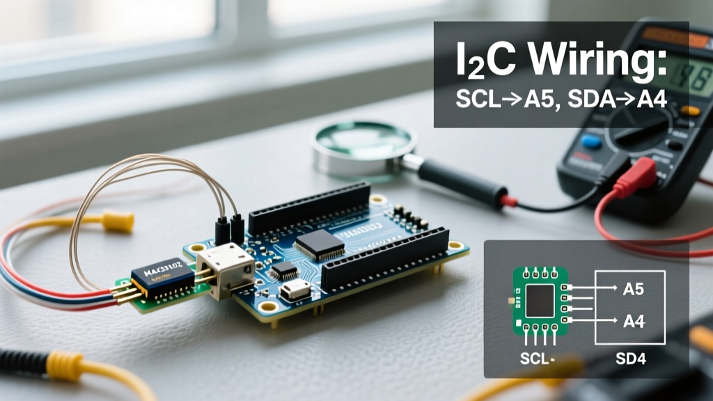
- SDA: Connect to SDA (A4 on standard Nano, dedicated SDA on IoT)
- SCL: Connect to SCL (A5 on standard Nano, dedicated SCL on IoT)
- INT: Connect to Digital Pin 2 (Hardware Interrupt 0)
Core Configuration Parameters in the SparkFun Library
To interface with the sensor, we utilize the industry-standard SparkFun MAX3010x library. Simply calling sense.begin() is not enough; you must configure the internal registers to match your specific physical housing and finger optics. Below are the critical parameters you must tune.
1. LED Pulse Amplitude Tuning (Current Control)
The MAX30102 drives its internal Red and IR LEDs using programmable current sinks ranging from 0mA to 50mA. The current is set via an 8-bit register (0x00 to 0xFF). The formula for the actual current output is: Current (mA) = (Register Value) * (50mA / 256).
If the current is too high, the 18-bit ADC will saturate (clip at 32768), resulting in a flatlined signal. If it is too low, the signal-to-noise ratio (SNR) will be swallowed by ambient light noise. For a standard transmissive or reflective finger clip, the following baseline values are highly recommended:
sense.setPulseAmplitudeRed(0x0A);(Approx. 1.95mA - Red light scatters easily, requires less power)sense.setPulseAmplitudeIR(0x1F);(Approx. 6.05mA - IR penetrates tissue deeper, requires more power)sense.setPulseAmplitudeProximity(0x1F);
2. Sample Rate and ADC Range
The Nyquist-Shannon sampling theorem dictates that your sample rate must be at least twice the highest frequency component of your signal. A human heart rate maxes out around 220 BPM (3.66 Hz). However, to capture the "dicrotic notch" (the secondary wave in the PPG signal caused by the aortic valve closing), you need higher resolution.
According to the SparkFun MAX3010x Hookup Guide, configuring the sample rate to 100 SPS (Samples Per Second) with an ADC range of 4096 provides the perfect balance of processing overhead and waveform fidelity for an Arduino MCU.
sense.setAdcRange(ADC_RANGE_4096);(Prevents clipping on highly vascular subjects)sense.setSampleRate(SAMPLE_RATE_100);sense.setSampleAveraging(SAMPLE_AVG_4);(Averages 4 samples to smooth out high-frequency electrical noise)
Step-by-Step Firmware Initialization
Below is the optimized initialization sequence to place in your setup() function. This sequence ensures the FIFO (First-In-First-Out) buffer is properly managed and the sensor is primed for continuous interrupt-driven reading.
- Wire Initialization: Call
Wire.begin()and set the I2C clock speed to 400kHz viaWire.setClock(400000)to ensure rapid FIFO buffer offloading. - Sensor Reset: Call
sense.softReset()to clear any residual states from previous power cycles. - Apply Tuning Parameters: Inject the LED current, ADC, and SPS configurations detailed in the previous section.
- FIFO Management: Configure the FIFO rollover to prevent data lockups. Use
sense.enableFIFORollover()so that when the 32-sample buffer fills, it overwrites the oldest data rather than halting collection. - Interrupt Attachment: Attach your hardware interrupt pin to a volatile boolean flag.
attachInterrupt(digitalPinToInterrupt(2), markFIFO, FALLING);
Troubleshooting Signal Clipping and Noise
Even with perfect code, physical configuration errors will ruin your PPG waveform. Use this diagnostic matrix to identify and resolve common hardware-level issues in your heart rate monitor Arduino build.
- Symptom: ADC constantly reads 32767 (Signal Clipping).
Cause: LED current is too high, or the sensor is pressed too tightly against the skin, causing maximum light reflection.
Fix: ReducesetPulseAmplitudeIRfrom 0x1F to 0x15. Add a 2mm foam spacer between the sensor and the finger to establish a fixed focal distance. - Symptom: Signal is entirely flat or reads 0.
Cause: The sensor is not detecting a finger, triggering the internal proximity power-saving mode, OR the I2C address is mismatched (0x57 vs 0x56).
Fix: IncreasesetPulseAmplitudeProximityto 0x33 to boost the IR proximity threshold. Run an I2C scanner sketch to verify the sensor's hexadecimal address on the bus. - Symptom: Massive 50Hz/60Hz AC Mains Noise.
Cause: The USB power supply from your PC or wall brick is injecting switching noise into the 3.3V rail, which the sensor's internal LDO cannot filter.
Fix: Power the Arduino via a high-quality linear voltage regulator or a battery bank rather than a cheap switching wall adapter. Add a 100nF ceramic capacitor directly across the VIN and GND pins on the MAX30102 breakout. - Symptom: Heart Rate calculation fluctuates wildly (e.g., 60 to 140 BPM in seconds).
Cause: Motion artifacts. The Arduino's peak-detection algorithm is mistaking physical movement for cardiac systoles.
Fix: Implement a moving average filter in your software logic, or use an accelerometer (like the onboard IMU on the Nano 33 IoT) to gate the HR calculation, only processing PPG data when the device is physically stationary.
Final Thoughts on Biometric Maker Projects
Configuring a heart rate monitor Arduino system using the MAX30102 is a masterclass in bridging the gap between raw biomedical hardware and high-level microcontroller logic. By respecting the 1.8V logic constraints, mathematically tuning the LED current registers, and properly managing the I2C FIFO buffer, you elevate your project from a blinking LED toy to a legitimate biometric data acquisition tool. Always prioritize signal integrity at the hardware level; no amount of software filtering can recover a PPG waveform that has been clipped by an overdriven IR LED.