
The Reality of MEMS Inertial Navigation on Microcontrollers
Building a reliable inertial navigation Arduino system is one of the most rewarding, yet mathematically unforgiving, challenges in embedded robotics. Unlike simple orientation tracking (which only requires sensor fusion for pitch, roll, and yaw), true inertial navigation requires calculating position over time through dead reckoning. This demands double-integration of accelerometer data—a process that amplifies microscopic MEMS sensor noise into massive positional drift within seconds.
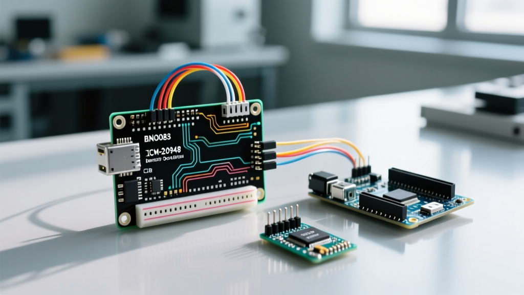
As of 2026, the legacy BNO055 has been largely superseded by advanced sensor hubs like the CEVA BNO085/BNO086 and the TDK ICM-20948. These modern ICs offload complex Kalman filtering and sensor fusion to dedicated onboard DSPs, freeing your Arduino's CPU for high-level navigation logic. This guide details the exact hardware selection, I2C bus conditioning, and algorithmic configurations required to build a functional Arduino-based Inertial Navigation System (INS).
Hardware Selection: Sensor Hubs vs. Raw IMUs
To achieve navigational grade tracking, you must avoid raw IMUs that require the Arduino to perform manual sensor fusion (like the outdated MPU6050). You need an IMU paired with a dedicated Sensor Hub running proprietary fusion algorithms.
| Component | Architecture | 2026 Avg. Price | Best Use Case | Navigation Grade |
|---|---|---|---|---|
| Adafruit BNO085 | CEVA Sensor Hub + Triad MEMS | $44.95 | AR/VR tracking, Rover dead reckoning | High (Tactical/Consumer) |
| SparkFun ICM-20948 | TDK IMU + AK09916 Mag | $24.95 | Custom Kalman filtering, Drone telemetry | Medium (Requires external DSP) |
| BNO055 (Legacy) | Bosch Sensortec | $34.95 (Scarce) | Basic orientation (Not recommended for new nav) | Low (Discontinued) |
For a turnkey inertial navigation Arduino project, the Adafruit BNO085 9-DOF IMU is the premier choice. Its onboard CEVA DSP outputs pre-calculated quaternions and linear acceleration, which are mandatory for minimizing integration drift.
Wiring and I2C Bus Conditioning
The most common point of failure in Arduino INS setups is I2C bus instability. The BNO085 utilizes HID (Human Interface Device) over I2C, a protocol that is highly sensitive to bus capacitance and missing pull-up resistors.
Critical I2C Configuration Rules
- Voltage Logic: The BNO085 is strictly a 3.3V device. If you are using a 5V Arduino Uno or Mega, you must use a bi-directional logic level converter (e.g., NXP PCA9306). Direct 5V connection will degrade the I2C transceivers and cause silent data corruption.
- Pull-Up Resistors: While breakout boards include 10kΩ pull-ups, these are too weak for 400kHz Fast Mode I2C. Solder additional 2.2kΩ resistors between the SDA/SCL lines and 3.3V to achieve sharp signal rise times.
- Reset Pin Management: The BNO085 requires a specific hardware reset sequence upon boot. Connect the IMU's
RSTpin to Arduino Digital Pin 4. The library requires toggling this pin LOW for 10ms, then HIGH, before initializing the I2C bus.
Configuring the BNO085 Sensor Hub for Navigation
Unlike raw sensors where you simply poll registers, the BNO085 uses a report-based system. You must explicitly tell the sensor hub which data streams to enable and at what frequency. For dead reckoning, we need the Game Rotation Vector (for orientation without magnetic interference) and Linear Acceleration (gravity removed).
Step-by-Step Report Configuration
- Install the Library: Use the
Adafruit BNO08xlibrary via the Arduino IDE Library Manager. - Initialize I2C Mode: Pass the correct I2C address (usually
0x4Aor0x4B) and the reset pin to the constructor. - Enable Navigation Reports: Configure the sensor to output data at 100Hz (10ms intervals). Anything lower will cause aliasing during high-speed maneuvers.
// BNO085 Configuration Snippet for Navigation
bno08x.enableReport(SH2_GAME_ROTATION_VECTOR, 10000); // 100Hz
bno08x.enableReport(SH2_LINEAR_ACCELERATION, 10000);  // 100Hz
bno08x.enableReport(SH2_GYROSCOPE_CALIBRATED, 10000); // 100Hz
Expert Insight: Do not use the standardSH2_ROTATION_VECTORfor indoor rovers. It relies on the magnetometer, which will be easily saturated by the electromagnetic fields of your rover's DC motors or steel chassis. TheSH2_GAME_ROTATION_VECTORfuses only the accelerometer and gyroscope, preventing magnetic hard-iron distortion from snapping your heading 180 degrees.
Overcoming Double-Integration Drift
According to the principles outlined in the VectorNav Inertial Navigation Primer, calculating position from an IMU requires integrating acceleration to get velocity, and integrating velocity to get position. Because MEMS accelerometers have a bias instability (noise), integrating this noise results in quadratic positional drift. A high-end consumer IMU like the BNO085 can drift by several meters within just 15 seconds of dead reckoning.
Implementing ZUPT (Zero Velocity Update)
To make an Arduino INS viable, you must implement algorithmic constraints. The most effective technique for stop-and-go rovers or foot-mounted trackers is ZUPT.
- The Logic: Monitor the gyroscope and linear acceleration magnitude. If the angular velocity drops below 0.05 rad/s and linear acceleration variance approaches zero, the system infers the robot is stationary.
- The Correction: Force the integrated X and Y velocity variables to exactly
0.0. This prevents the "phantom velocity" caused by sensor bias from integrating into massive positional errors while the robot is stopped at an intersection or waypoint.
Fusing Odometry via Extended Kalman Filter (EKF)
For continuous motion, pure INS is insufficient on a microcontroller budget. You must fuse the BNO085's linear acceleration with wheel encoders. The TDK ICM-20948 is often preferred in advanced ROS 2 setups precisely because it allows raw data extraction to feed into an external EKF node, blending wheel ticks with IMU acceleration to bound the drift.
Edge Cases and Calibration Failures
Even with perfect code, physical environment factors will break your navigation stack if not mitigated.
1. Accelerometer Clipping (High-G Maneuvers)
The BNO085 default linear acceleration report is optimized for human motion (typically ±2G to ±4G). If your Arduino controls a high-speed RC car or a catapult mechanism, the accelerometer will "clip" at its maximum range. The sensor hub will report the maximum value continuously, leading to catastrophic velocity overestimation. Fix: Use the BNO08x dynamic range configuration commands to set the accelerometer to ±8G or ±16G before enabling the navigation reports.
2. Thermal Bias Shift
MEMS sensors exhibit significant bias drift as their silicon die heats up. When you first power on your Arduino rover, the IMU will be at ambient temperature. As the onboard voltage regulators and the IMU's internal DSP heat up over the first 5 minutes, the Z-axis accelerometer bias will shift, causing the navigation algorithm to think the rover is slowly accelerating upward or tilting. Fix: Implement a 3-minute "warm-up" state in your Arduino state machine where position integration is paused, allowing the sensor hub's internal temperature compensation algorithms to stabilize.
3. Vibration Coupling
Mounting the IMU directly to a rigid aluminum chassis with vibrating motors will inject high-frequency noise into the accelerometer. The BNO085's internal low-pass filter can only do so much. Fix: Mount the IMU breakout board using closed-cell foam tape or specialized silicone dampening standoffs to isolate it from chassis resonance frequencies above 50Hz.
Summary Checklist for Deployment
- Verify 3.3V logic levels and 2.2kΩ I2C pull-ups.
- Use Game Rotation Vector to avoid motor-induced magnetic distortion.
- Implement ZUPT logic to kill velocity drift during stationary periods.
- Allow a 3-minute thermal stabilization window before recording start coordinates.
- Isolate the sensor hub from high-frequency mechanical vibrations.
By respecting the physical limitations of MEMS technology and leveraging the onboard DSP of modern sensor hubs, your Arduino-based inertial navigation system can achieve remarkably accurate dead reckoning for indoor robotics and autonomous rover applications.