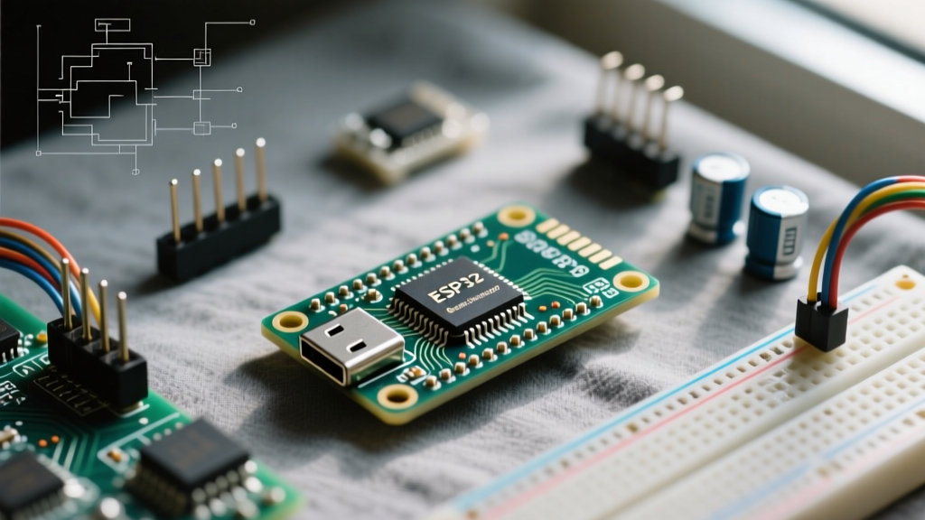

The Anatomy of an ESP32 Boot Failure
When developing with the ESP32, encountering a frozen sketch, a continuous boot loop, or the dreaded 'Timed out waiting for packet header' error in the Arduino IDE is a rite of passage. Understanding how to reset ESP32 hardware is not just about pressing a physical button; it requires a deep diagnostic approach to the microcontroller's boot sequence, strapping pins, and UART bridge circuitry. Unlike simpler 8-bit microcontrollers, the ESP32 relies on a complex Real-Time Clock (RTC) memory state, SPI flash execution, and a dual-core architecture that can easily desynchronize or lock up if interrupt service routines (ISRs) or Wi-Fi stacks are mismanaged.
Before attempting a hard reset, it is crucial to diagnose why the ESP32 requires resetting in the first place. Common failure modes include brownout detector (BOD) triggers caused by insufficient USB current delivery, corrupted SPIFFS/LittleFS partitions, and infinite loops lacking yield() or delay() calls, which starve the FreeRTOS background tasks and trigger the Task Watchdog Timer (TWDT). By isolating the failure domain—whether it is hardware-level strapping, USB-to-UART bridge logic, or software-level memory leaks—you can apply the correct reset methodology to recover your board.
Hardware Reset Methods: From Auto-Reset to Manual Intervention
The primary hardware reset mechanism on the ESP32 is the EN (Enable) pin, also known as CHIP_PU. Pulling this pin LOW for at least 200 microseconds forces the internal voltage regulators to shut down, clearing the CPU registers and RTC fast memory. When EN is pulled HIGH again, the chip initiates its boot sequence. However, the state of the ESP32 upon waking is entirely dictated by its strapping pins.
The EN and GPIO Strapping Pin Matrix
Espressif designs the ESP32 to sample specific GPIO pins during the reset release phase to determine the boot mode. If your ESP32 is stuck in a boot loop or failing to enter flash mode, you must verify that external peripherals are not forcing these pins into conflicting states. Below is the critical strapping pin matrix derived from the official Espressif ESP32 Datasheet.
| GPIO Pin | Normal Boot (SPI Flash) | Download Boot (UART Flash) | Common Diagnostic Conflict |
|---|---|---|---|
| GPIO0 | High / Float | Low | External pull-down resistors or I2C devices holding it LOW. |
| GPIO2 | Low / Float | Low / Float | Onboard LEDs or relays pulling HIGH, preventing flash mode. |
| GPIO12 (MTDI) | Float / Low (3.3V Flash) | High (1.8V Flash) | Accidental HIGH triggers 1.8V mode, causing brownouts on 3.3V boards. |
| GPIO15 (MTDO) | High / Float (Log Output) | Low (Silent Boot) | Active LOW peripherals suppressing boot logs, masking errors. |
Diagnostic Pro-Tip: If your ESP32 resets but immediately outputs garbage characters or fails to execute code, check GPIO12. If an external sensor is pulling GPIO12 HIGH during boot, the ESP32 will attempt to power its internal SPI flash at 1.8V instead of 3.3V, leading to immediate flash read failures and continuous resetting.
Diagnosing the 'Failed to Connect' UART Error Loop
A frequent scenario where makers need to know how to reset ESP32 manually is during firmware uploading. The Arduino IDE relies on the auto-reset circuit to seamlessly transition the ESP32 from execution mode to download boot mode. This circuit utilizes the DTR and RTS control lines from the USB-to-UART bridge (typically a CP2102N or CH340G chip) to manipulate the EN and GPIO0 pins via NPN transistors.
When the IDE initiates an upload, the sequence is as follows:
- RTS goes LOW, pulling EN LOW (Resetting the ESP32).
- DTR goes LOW, pulling GPIO0 LOW (Setting Flash Mode).
- RTS goes HIGH, releasing EN HIGH (Booting the ESP32).
- The ESP32 samples GPIO0 (which is still LOW) and enters the UART bootloader.
The Missing Capacitor Failure Mode
Many third-party ESP32 development boards (especially early NodeMCU-32S clones) suffer from a flawed auto-reset circuit design. The Espressif reference design requires a specific RC delay—usually a 10kΩ resistor and a 1µF to 10µF capacitor on the EN line—to ensure the timing of the DTR and RTS signals overlaps correctly. If your board lacks this capacitor, the EN pin releases before GPIO0 stabilizes, causing the ESP32 to boot into normal SPI execution mode instead of download mode. The IDE then throws a 'Timed out waiting for packet header' error.
The Manual Override Fix: To bypass a broken auto-reset circuit, you must perform a synchronized manual reset. Click 'Upload' in the Arduino IDE. When the console displays 'Connecting...', press and hold the 'BOOT' button (which grounds GPIO0). While holding BOOT, press and release the 'EN' or 'RST' button. Finally, release the BOOT button. This manually replicates the DTR/RTS transistor logic and forces the strapping pins into download mode.
Software-Initiated Resets and Watchdog Timers
In deployed IoT environments, physical buttons are inaccessible. Therefore, understanding software reset vectors is vital for remote error diagnosis and recovery. The Arduino ESP32 core provides several methods to trigger a reset programmatically, each with distinct behaviors regarding RTC memory retention.
ESP.restart() vs. esp_restart()
The standard ESP.restart() function is a wrapper around the ESP-IDF's esp_restart() method. According to the ESP-IDF System API documentation, this function performs a software reset by triggering the digital core reset. It does not power cycle the chip. Consequently, RTC slow memory and RTC fast memory are preserved across this reset. If your code relies on a clean power-on state, a software reset might leave corrupted variables in RTC memory, causing the same boot loop to trigger immediately upon restart.
Task Watchdog Timer (TWDT) Diagnostics
If your ESP32 is resetting unexpectedly, the Task Watchdog Timer is often the culprit. The TWDT monitors the FreeRTOS idle tasks. If a high-priority task (like a Wi-Fi event handler or a heavy for loop) blocks the CPU core for longer than the default timeout (usually 5 seconds), the TWDT triggers a system panic and resets the chip. You will see an error in the serial monitor resembling:
task_wdt: Task watchdog got triggered. The following tasks did not reset the watchdog in time...
To diagnose and prevent this, ensure you are feeding the watchdog in long-running loops using yield(), vTaskDelay(), or esp_task_wdt_reset(). You can also adjust the TWDT timeout via the Arduino IDE Tools menu under 'Task Watchdog timeout duration' to isolate whether a reset is caused by a genuine hardware fault or a software bottleneck.
Advanced Recovery: Erasing Flash and Deep Sleep Wakeups
Sometimes, a corrupted file system or a bad Over-The-Air (OTA) update partition renders the ESP32 completely unresponsive, resetting endlessly before the serial monitor can even connect. In these catastrophic failure modes, standard reset procedures are insufficient.
Full Flash Erasure
If strapping pin manipulation and manual BOOT/EN sequences fail to stabilize the board, the SPI flash memory itself may contain conflicting partition tables. Using the Arduino ESP32 Core tools, select 'Erase All Flash Before Sketch Upload' from the Tools menu. This forces the esptool.py script to issue a erase_flash command via the UART bootloader, wiping the bootloader, partitions, and SPIFFS/LittleFS data, providing a true clean slate.
Deep Sleep as a Reset Mechanism
For battery-operated diagnostic nodes, utilizing esp_deep_sleep_start() acts as a functional reset. Unlike ESP.restart(), deep sleep powers down almost all internal peripherals, including the CPU and SPI flash. The chip is effectively 'off' until an external wake source (RTC GPIO, Ext0/Ext1, or a timer) pulls it out of sleep. Upon waking, the ESP32 executes a full hardware boot sequence, starting from the very first line of setup(). This is the most reliable way to clear peripheral lockups (such as a frozen I2C bus or locked SPI bus) without requiring a physical power cycle.
Summary of Diagnostic Reset Actions
- Frozen Sketch / No Serial Output: Check for infinite loops missing
yield(). Press the physical EN button. - 'Timed out waiting for packet header': Auto-reset circuit failure. Use the manual BOOT + EN button sequence.
- Garbage Characters on Boot: GPIO12 strapping pin conflict. Remove external peripherals from GPIO12 and reset.
- Continuous Brownout Resets: Insufficient USB power or GPIO15/GPIO12 misconfiguration. Power via a dedicated 5V/2A supply and reset.
- Corrupted OTA / Filesystem: Perform a full 'Erase All Flash' via the Arduino IDE after forcing UART download mode.
Mastering how to reset ESP32 hardware and software states transforms frustrating development roadblocks into predictable, solvable engineering problems. By respecting the strapping pin matrix and understanding the underlying FreeRTOS watchdog mechanics, you can build resilient, self-recovering IoT architectures.