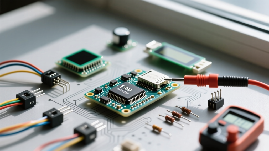

The "It Works on Uno but Fails on ESP32" Dilemma
If you have spent any time in maker forums, Discord servers, or GitHub issue trackers, you know the ESP32 is a powerhouse. However, migrating from 5V AVR boards to the 3.3V ESP32 often triggers a frustrating rite of passage: the dreaded I2C bus failure. Sensors like the BME280, SHT31, or OLED displays that worked flawlessly on an Arduino Uno suddenly return 0xFF, fail to initialize, or cause the ESP32 to watchdog-reset. This community resource distills thousands of forum threads, hardware hacks, and software patches into a definitive guide to mastering ESP32 I2C.
The GPIO Matrix & Pinout Reality
Unlike the rigid hardware I2C pins on older microcontrollers, the ESP32 features a highly flexible GPIO Matrix. This means you can route the I2C peripheral to almost any available pin via software. However, relying on default pins without understanding the silicon variant you are using is a common trap.
| MCU Variant | Default SDA | Default SCL | Community Recommended Pins | Notes & Conflicts |
|---|---|---|---|---|
| Original ESP32 | GPIO 21 | GPIO 22 | 21 / 22 | Safe for most breakout boards. Avoid strapping pins. |
| ESP32-S3 | GPIO 8 | GPIO 9 | 1 / 2 or 38 / 39 | Pins 8/9 are often routed to Octal SPI Flash/PSRAM on WROOM modules. |
| ESP32-C3 | GPIO 4 | GPIO 5 | 4 / 5 or 6 / 7 | Limited GPIO count; ensure pins aren't used for USB-JTAG. |
| ESP32-S2 | GPIO 8 | GPIO 9 | 1 / 2 or 11 / 12 | Similar Flash/PSRAM routing conflicts as the S3. |
The Strapping Pin Trap
A frequent community headache involves assigning I2C to strapping pins (e.g., GPIO 0, 2, 12, and 15 on the original ESP32). During boot, the ESP32 reads the voltage levels on these pins to determine boot modes (e.g., SPI flash vs. serial bootloader). If your I2C pull-up resistors pull a strapping pin HIGH when the chip expects it LOW (or vice versa), your ESP32 will enter an infinite boot loop. Always cross-reference your chosen I2C pins with the Espressif I2C Documentation to ensure they are safe for general-purpose I/O.
Hardware Design: The Physics of the Pull-Up
The open-drain nature of I2C requires pull-up resistors. The community default of "just use 4.7kΩ" is a legacy habit from 5V, 100kHz Standard Mode buses. When running an ESP32 at 3.3V and 400kHz Fast Mode, 4.7kΩ often results in sluggish rise times, violating the I2C specification and causing silent data corruption.
According to the NXP I2C Bus Specification (UM10204), the maximum bus capacitance is 400pF. Every wire, breadboard contact, and sensor module adds 10pF to 50pF of capacitance. To calculate the minimum pull-up resistor required to sink 3mA while keeping the output low voltage ($V_{ol}$) under 0.4V:
Formula: $R_{min} = (V_{cc} - V_{ol}) / I_{ol}$
For 3.3V ESP32: $R_{min} = (3.3V - 0.4V) / 0.003A = 966\Omega$
While 1kΩ is the absolute mathematical floor, the community consensus for 3.3V ESP32 projects running at 400kHz is to use 2.2kΩ pull-up resistors. This provides a fast enough RC rise time to meet the 300ns maximum rise time requirement of Fast Mode I2C, while staying well within the 3mA sink limit of the ESP32 GPIO pins.
Software Quirks: Wire.h Syntax & Clock Stretching
The Arduino Wire.h library behaves differently on the ESP32 Arduino Core compared to AVR. The ESP32 implementation allows you to define pins and frequency directly in the begin() method.
<pre>
#include <Wire.h>

#define SDA_PIN 21
#define SCL_PIN 22
#define I2C_FREQ 400000 // 400kHz Fast Mode

void setup() {
  Serial.begin(115200);

  // ESP32 specific Wire.begin syntax
  Wire.begin(SDA_PIN, SCL_PIN, I2C_FREQ);

  // Crucial for sensors that use clock stretching (e.g., BME280, SHT3x)
  Wire.setClockStretchLimit(150000);

  Serial.println("I2C Bus Initialized");
}
</pre>
Fixing the Infamous Clock Stretching Timeout
Clock stretching is a mechanism where a slave device holds the SCL line LOW to pause the master while it processes data. Early versions of the ESP32 Arduino Core had a severe bug where the underlying FreeRTOS I2C driver would time out and crash if a sensor stretched the clock for more than a few milliseconds. This caused widespread failures with environmental sensors like the BME280.
While modern ESP32 cores (v2.0.0 and above) have largely patched the underlying ESP-IDF driver, adding Wire.setClockStretchLimit(150000); remains a community-recommended best practice. This extends the timeout threshold to 150 milliseconds, ensuring your sketch doesn't hard-fault when a sensor is busy performing internal ADC conversions or calibration routines.
Advanced Topologies: Level Shifting & Multiplexing
Because the ESP32 is strictly a 3.3V device, connecting it directly to 5V I2C sensors (like older LCD backpacks or certain automotive modules) will destroy the ESP32's GPIO pins. The community strongly advises against using simple resistor dividers for I2C due to the bidirectional nature of the SDA line. Instead, use a dedicated bidirectional logic level shifter like the PCA9306 or the widely available BSS138 MOSFET-based modules.
If you need to connect multiple identical sensors (e.g., three BME280s for multi-zone climate monitoring), they will share the same I2C address. Rather than hacking the physical address jumpers, the community standard is to use the TCA9548A I2C Multiplexer. This chip sits on the main bus and allows you to route the I2C signals to 8 separate sub-buses via software commands.
The Community "No-Device-Found" Checklist
When your I2C scanner returns nothing, or your sensor library throws a -1 error, run through this battle-tested checklist before blaming the hardware:
- Verify Voltage: Are you powering the sensor with 3.3V? If it's a 5V sensor, are you using a proper bidirectional level shifter?
- Check Pull-Ups: Do you have physical 2.2kΩ or 4.7kΩ resistors on SDA and SCL? (Note: Many cheap breakout boards include them, but cheap logic shifters often do not).
- Inspect the Wiring: SDA and SCL are swapped. This is the #1 cause of failure. Use a multimeter in continuity mode to trace the exact paths.
- Lower the Clock Speed: Temporarily drop
I2C_FREQto100000(100kHz). If it works at 100kHz but fails at 400kHz, you have a bus capacitance or pull-up resistor issue. - Run the Bus Scanner: Upload the standard Arduino I2C Scanner sketch. If the ESP32 hangs entirely during the scan, you likely have a short circuit on the SDA line or a slave device is holding the bus LOW in a locked state. Power cycle the entire breadboard.
By understanding the physical layer requirements and the specific software quirks of the ESP32 Arduino Core, you can bypass the most common pitfalls. For deeper dives into the underlying RTOS drivers, consult the Arduino Wire Reference and the Espressif API docs.