
The Anatomy of the ESP32 DevKit V1
When you purchase an ESP32 development board, you are most likely getting a variant of the ubiquitous ESP32 DevKit V1. Priced between $5 and $8, these boards pack an incredible amount of processing power, Wi-Fi, and dual-mode Bluetooth into a breadboard-friendly footprint. However, the sheer density of features means that the ESP32 DevKit pinout is far more complex than a standard Arduino Uno. Not all pins are created equal, and treating them as generic I/O is the fastest way to introduce erratic behavior into your embedded projects.
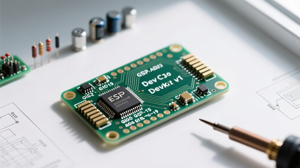
At the heart of the board sits the ESP-WROOM-32 (or ESP-WROOM-32D) module, recognizable by its metal RF shield. This module contains the ESP32 SoC, the SPI flash memory, and the PCB trace antenna. Surrounding the module on the carrier board are two critical components: a 5V-to-3.3V Low Dropout (LDO) voltage regulator (typically an AMS1117-3.3) and a USB-to-UART bridge chip. It is vital to remember that the ESP32 operates strictly on 3.3V logic levels. Feeding 5V directly into a standard GPIO pin will permanently damage the silicon. Always use logic level shifters when interfacing with 5V sensors or modules.
Decoding the Layout: 30-Pin vs. 38-Pin Variations
One of the most confusing aspects for beginners navigating the ESP32 DevKit pinout is discovering that not all DevKits are physically identical. The market is flooded with two primary form factors:
- The 38-Pin DOIT DevKit V1: This is the classic, wider board. It exposes almost every pin from the ESP-WROOM-32 module, including GPIOs 6 through 11.
- The 30-Pin NodeMCU-32S Style: This narrower board is much more common in modern maker kits. It intentionally hides GPIOs 6 through 11.
Why hide pins? GPIOs 6, 7, 8, 9, 10, and 11 are internally hardwired to the integrated SPI flash memory on the ESP32 module. If you attempt to use these pins for external sensors, LEDs, or displays, the microcontroller will crash, throw a Guru Meditation Error, or fail to boot entirely. The 30-pin boards do makers a favor by physically omitting these dangerous pins from the headers. If you are using a 38-pin board, treat GPIOs 6-11 as strictly off-limits.
The Danger Zone: Understanding Strapping Pins
Unlike traditional microcontrollers that feature a dedicated hardware BOOT pin, the ESP32 relies on a clever but restrictive system called strapping pins. During a hard reset or power-on event, the ESP32's ROM bootloader samples the voltage levels on specific GPIO pins to determine its boot mode. If you have external circuits pulling these pins to the wrong state, your code will never execute.
According to the Espressif ESP32 Datasheet, the primary strapping pins are:
- GPIO 0: Determines if the chip enters Serial Bootloader mode (for flashing new code via UART) or boots normally from the SPI flash. It must be HIGH (or floating, relying on internal pull-ups) for normal operation. If pulled LOW during boot, the ESP32 waits for a serial upload.
- GPIO 2: Must be LOW or floating to boot from SPI flash. Connecting a component that pulls GPIO 2 HIGH on startup will prevent the board from booting.
- GPIO 12 (MTDI): This is the most dangerous strapping pin. It dictates the flash voltage. Most ESP32 modules use 3.3V SPI flash. If GPIO 12 is pulled HIGH during boot, the ESP32 switches the internal voltage regulator to 1.8V, causing the flash chip to fail and the boot process to halt.
- GPIO 15 (MTDO): Configures the boot log printing to UART0. Pulling it LOW silences the boot logs, which is generally harmless but can make debugging difficult.
Maker Rule of Thumb: Never connect relays, motors, or high-current LEDs directly to GPIO 0, 2, or 12. If a relay triggers a LOW state on GPIO 0 during the exact millisecond the ESP32 resets, your device will enter flash mode instead of running your sketch.
The ADC Quirk: Why Your Sensors Fail When Wi-Fi Connects
A classic rite of passage for ESP32 makers is building an analog sensor project that works perfectly on the bench, only to fail the moment the Wi-Fi connects. This is not a bug in your code; it is a fundamental hardware limitation of the ESP32 DevKit pinout regarding Analog-to-Digital Converters (ADC).
The ESP32 features two ADC units: ADC1 and ADC2.
- ADC1 (GPIO 32, 33, 34, 35, 36, 39): These pins are dedicated to analog reading and are completely safe to use alongside Wi-Fi and Bluetooth.
- ADC2 (GPIO 0, 2, 4, 12, 13, 14, 15, 25, 26, 27): These pins share hardware resources with the Wi-Fi MAC layer. When the Wi-Fi radio is active, it hijacks the ADC2 controller for internal RF calibration and timing. Any attempt to read an ADC2 pin while Wi-Fi is enabled will return garbage data or fail silently.
As detailed in the ESP-IDF GPIO API Reference, if your project requires both Wi-Fi connectivity and analog sensor readings, you must route your analog sensors exclusively to ADC1 pins (GPIO 32-39). Note that GPIO 34, 35, 36, and 39 are input-only pins and lack internal pull-up/pull-down resistors.
Peripheral Defaults and the GPIO Matrix
The ESP32 features a highly advanced internal multiplexing system known as the GPIO Matrix. This allows you to map almost any internal peripheral (I2C, SPI, UART, I2S) to almost any digital pin via software. However, for the sake of sanity and compatibility with standard Arduino libraries, the community has adopted default pin assignments for the ESP32 DevKit V1:
- Default I2C: SDA on GPIO 21, SCL on GPIO 22. (These pins have internal 4.7k pull-up resistors on most DevKit boards, making them ideal for OLED displays and BME280 sensors).
- Default SPI (VSPI): MOSI on GPIO 23, MISO on GPIO 19, SCK on GPIO 18, CS on GPIO 5.
- Default UART0 (Serial Monitor): TX on GPIO 1, RX on GPIO 3.
- Default UART2: TX on GPIO 17, RX on GPIO 16. (Perfect for connecting GPS modules or secondary microcontrollers).
Comprehensive ESP32 Safe Pin Reference Table
To save you hours of debugging, refer to this quick-reference table when designing your next wiring harness or custom PCB. For more visual diagrams, the Random Nerd Tutorials ESP32 Pinout Guide remains an excellent community resource.
| GPIO Pin | Primary Function | Boot / Strapping Behavior | Safe for General Use? |
|---|---|---|---|
| GPIO 1, 3 | UART0 (USB Serial) | Outputs boot logs | No (Reserved for USB debug) |
| GPIO 2 | Onboard LED / ADC2 | Must be LOW to boot | Use with caution |
| GPIO 4, 13-15, 25-27 | ADC2 / Touch / DAC | Various strapping roles | Safe (If Wi-Fi ADC2 quirk is managed) |
| GPIO 6-11 | Integrated SPI Flash | N/A | NEVER USE |
| GPIO 12 | ADC2 / Touch / Strapping | Alters Flash Voltage (MTDI) | No (High risk of boot failure) |
| GPIO 16, 17 | UART2 (Hardware Serial) | None | YES (Highly Recommended) |
| GPIO 18, 19, 23 | VSPI (Default SPI Bus) | None | YES (Highly Recommended) |
| GPIO 21, 22 | Default I2C Bus | None | YES (Highly Recommended) |
| GPIO 32, 33 | ADC1 / Touch / XTAL | None | YES (Safe for Analog) |
| GPIO 34-39 | ADC1 (Input Only) | None | YES (Safe for Analog Sensors) |
Advanced Features: Capacitive Touch and DAC
Beyond standard digital I/O, the ESP32 DevKit pinout exposes hardware features rarely found on competing microcontrollers. The chip includes a 10-channel capacitive touch controller. Pins like GPIO 4, 13, 14, 15, 27, and 32 can detect the electrical capacitance of a human finger through a thin layer of plastic or glass, eliminating the need for physical mechanical buttons. Furthermore, GPIO 25 and 26 are connected to an 8-bit Digital-to-Analog Converter (DAC). Unlike PWM (which simulates analog via rapid switching), the DAC outputs a true, steady analog voltage between 0V and 3.3V, making it perfect for generating basic audio waveforms or driving analog synthesizer control voltage (CV) inputs.
Final Best Practices for Makers
Mastering the ESP32 DevKit pinout is about understanding the silicon's priorities. The chip prioritizes booting from flash, managing RF calibration, and maintaining Wi-Fi timing above all else. By avoiding strapping pins for external actuators, restricting analog sensors to ADC1, and utilizing the default I2C/SPI buses, you will eliminate 90% of the hardware-level bugs that plague beginner ESP32 projects. Always consult the specific schematic of your exact DevKit clone, as USB-bridge chips and onboard LED assignments can vary slightly between manufacturers.