
Why the ESP32-C3 SuperMini is Displacing the ESP8266
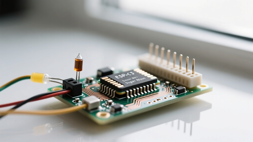
The ESP32-C3 SuperMini has rapidly become the go-to board for compact, low-power IoT projects. Built around the ESP32-C3FH4 chip, this board replaces the aging Xtensa architecture of the ESP8266 with a modern, single-core RISC-V processor running at 160 MHz. For makers and engineers, the transition offers a massive leap in security (secure boot and flash encryption) and power efficiency, all while maintaining a footprint barely larger than a postage stamp (typically 22.5 x 18mm).
Unlike the dual-core ESP32-WROOM, the C3 variant sacrifices raw multi-threading power for a lower quiescent current and a significantly reduced bill of materials (BOM). With retail prices hovering between $1.50 and $2.50 on platforms like AliExpress, it is currently the most cost-effective way to deploy Wi-Fi 4 and Bluetooth 5 (BLE) nodes in the field.
| Feature | ESP8266 (NodeMCU) | ESP32-WROOM (DevKit) | ESP32-C3 SuperMini |
|---|---|---|---|
| Architecture | Xtensa L106 (32-bit) | Xtensa LX6 (Dual-Core) | RISC-V (Single-Core) |
| Clock Speed | 80 / 160 MHz | 240 MHz | 160 MHz |
| SRAM | ~50 KB usable | 520 KB | 400 KB |
| Flash | 4 MB (Typical) | 4 MB (Typical) | 4 MB (Integrated SiP) |
| Native USB | No (Requires CP2102/CH340) | No (Requires CP2102/CH340) | Yes (GPIO18/19) |
| Deep Sleep Current | ~20 µA | ~10 µA | ~5 µA |
Hardware Pinout and Strict 3.3V Power Limitations
When wiring the ESP32-C3 SuperMini, the most critical rule is respecting the 3.3V logic threshold. Unlike some 5V-tolerant AVR microcontrollers, the RISC-V GPIO pins on the C3 are strictly 3.3V. Feeding a 5V signal into GPIO4 or GPIO5 will permanently destroy the silicon.
Power Delivery and the Onboard LDO
The board features an onboard LDO (frequently the ME6211C33M5G in SOT-23-5 packaging) that steps the 5V USB-C input down to 3.3V. While the datasheet for this LDO claims a 500mA output, the tiny 0.8mm PCB traces and lack of copper pour for heatsinking mean you should realistically limit continuous 3.3V rail draws to 250mA - 300mA. If you are driving external peripherals like a 128x64 OLED and a BME280 sensor simultaneously, you are well within limits. However, connecting high-draw components like a GSM module directly to the 3.3V pin will cause immediate brownouts and random reboots.
Native USB vs. UART
The SuperMini utilizes GPIO18 (D-) and GPIO19 (D+) for native USB communication. This eliminates the need for an external USB-to-UART bridge chip, saving board space and power. However, it also means that standard hardware UART debugging on GPIO20 (RX) and GPIO21 (TX) is isolated from the USB port unless explicitly bridged in software.
Step-by-Step Arduino IDE Configuration for RISC-V
Because the ESP32-C3 uses a RISC-V architecture rather than the Xtensa cores found in older ESP32s, you must ensure your Arduino IDE is configured with the correct board definitions. As of the latest Arduino ESP32 Core, RISC-V support is fully integrated.
- Open Arduino IDE and navigate to File > Preferences.
- In the 'Additional boards manager URLs' field, paste the official Espressif index:
https://raw.githubusercontent.com/espressif/arduino-esp32/gh-pages/package_esp32_index.json - Open the Boards Manager, search for
esp32, and install the latest version (v2.0.14 or newer recommended for stable C3 support). - Select Tools > Board > ESP32 Arduino > ESP32C3 Dev Module.
Critical IDE Setting: By default, the Arduino core may route Serial output to the hardware UART pins rather than the USB-C port. To fix this, you must go to Tools > USB CDC On Boot and set it to Enabled. Without this, your Serial.println() debugging statements will vanish into the ether.
Troubleshooting the 'Failed to Connect' Boot Mode Error
The most common failure mode encountered by makers using the ESP32-C3 SuperMini is the IDE throwing a 'Failed to connect to ESP32: Timed out waiting for packet header' error during compilation.
The Root Cause: Full-sized ESP32 DevKits feature an auto-reset circuit utilizing DTR and RTS lines from the UART bridge to automatically pull the boot pins low and reset the chip into download mode. To save space and cost, the SuperMini clones omit this auto-reset circuit. Furthermore, the board often lacks a dedicated 'BOOT' button.
The Solution (Manual Bootloader Entry):
- Locate GPIO8 on the pinout silkscreen. On the ESP32-C3, GPIO8 is the strapping pin that dictates boot mode.
- Connect a jumper wire from GPIO8 to GND.
- Press and release the onboard RESET button (or briefly short the RST pin to GND if no button is present).
- The chip will now boot into UART Download Mode.
- Click 'Upload' in the Arduino IDE. Once the compilation finishes and begins flashing, you can remove the GPIO8 jumper.
For production deployments, it is highly recommended to wire a tactile switch between GPIO8 and GND to avoid the jumper-wire dance during firmware updates. For deeper architectural details on strapping pins, refer to the Espressif ESP32-C3 Documentation.
Building a Low-Power I2C Sensor Node
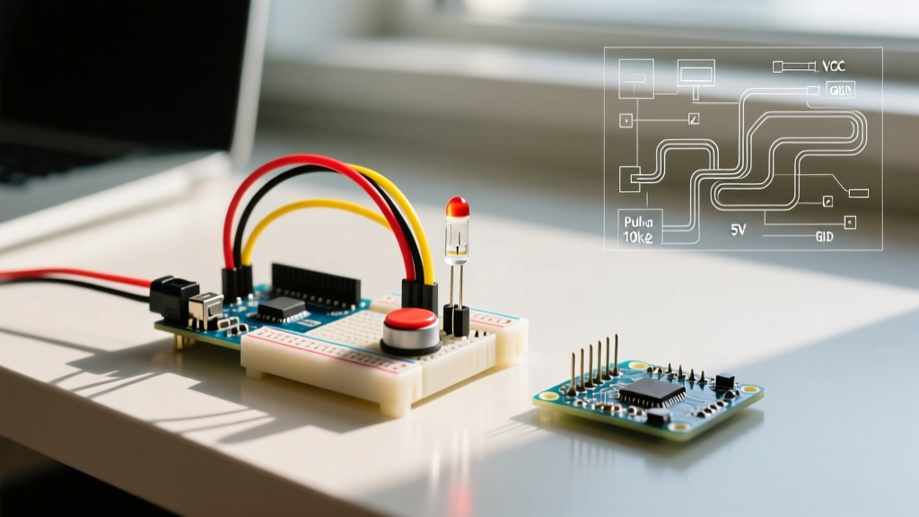
Let's apply this hardware to a practical scenario: wiring an I2C BME280 environmental sensor and preparing the board for deep sleep. The C3's I2C implementation is robust, but because it lacks internal pull-up resistors on most breakout boards, external 4.7kΩ resistors on SDA and SCL are mandatory for reliable bus communication.
Wiring the BME280 to the C3 SuperMini
- VIN / VCC: Connect to the 3.3V pin on the SuperMini.
- GND: Connect to any GND pin.
- SDA: Connect to GPIO6 (Default I2C SDA).
- SCL: Connect to GPIO7 (Default I2C SCL).
Deep Sleep Wake-Up Code Snippet
To maximize battery life, the ESP32-C3 can be put into deep sleep, drawing roughly 5 µA. Here is how to configure GPIO2 to wake the board from deep sleep using a reed switch or PIR sensor.
#include <Arduino.h>

#define WAKE_PIN 2

void setup() {
  Serial.begin(115200);
  delay(1000); // Allow USB CDC to initialize
  Serial.println('Booting from deep sleep or cold start...');

  // Perform sensor reading and Wi-Fi transmission here

  // Configure GPIO2 as wake-up source (HIGH state)
  esp_deep_sleep_enable_gpio_wakeup(1ULL << WAKE_PIN, ESP_GPIO_WAKEUP_GPIO_HIGH);

  Serial.println('Entering deep sleep...');
  Serial.flush();
  esp_deep_sleep_start();
}

void loop() {
  // This code will never be reached
}
For more advanced power management techniques and RTC memory retention, the Arduino ESP32 Official Docs provide extensive API references for the RISC-V core.
Thermal Throttling and RF Antenna Placement
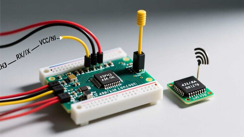
The ESP32-C3 SuperMini utilizes a PCB trace antenna (usually a meandering inverted-F design) located at the top edge of the board. Because the board is so small, the ground plane beneath the antenna is minimal, which can lead to impedance mismatches and reduced RF range compared to full-sized DevKits.
Deployment Rules for RF Integrity:
- Never enclose the antenna in metal. If you must use a metallic project box, position the SuperMini so the antenna protrudes through a non-conductive (plastic or resin) window.
- Keep the keep-out zone clear. Do not route ground pours or copper traces directly beneath the antenna trace on your custom carrier boards.
- Thermal Throttling: When transmitting Wi-Fi at +20 dBm continuously, the ESP32-C3FH4 chip can draw upwards of 350mA. On the SuperMini, this causes the silicon and the LDO to heat up rapidly. If you are designing a node that requires continuous, high-throughput TCP streaming, consider taping a small 10x10mm aluminum heatsink to the top of the black epoxy shield, or reduce the TX power via
WiFi.setTxPower(WIFI_POWER_8_5dBm)in your sketch to maintain thermal equilibrium.
By understanding the specific hardware quirks, power boundaries, and bootloader strapping requirements of the ESP32-C3 SuperMini, you can bypass the common frustrations of clone boards and deploy highly reliable, ultra-compact IoT sensors.