
The Core Concept: Beyond the 'Hello World' of Physical Computing
Building a button LED Arduino circuit is universally recognized as the rite of passage for embedded systems engineers and hobbyists alike. However, the vast majority of online tutorials treat this project as a trivial exercise, relying on blocking delay() functions and ignoring the underlying electrical engineering principles. This approach leads to fragile prototypes that fail in real-world environments due to floating pins, electromagnetic interference (EMI), and contact bounce.
In this comprehensive concept explainer, we will deconstruct the anatomy of a digital input. We will cover the physics of mechanical switch bounce, the necessity of pull resistors in CMOS logic, and how to write production-grade, non-blocking firmware using state-change detection. Whether you are using a classic ATmega328P-based Uno or the modern Renesas RA4M1-powered Arduino Uno R4 Minima, the electrical principles remain identical.
Floating Pins and the Danger of High Impedance
Microcontroller GPIO (General Purpose Input/Output) pins are built on CMOS (Complementary Metal-Oxide-Semiconductor) technology. When configured as an input, the pin exhibits extremely high impedance—often in the range of 100 megohms. If you wire a push button directly between a digital pin and ground, without any reference voltage, the pin becomes 'floating' when the switch is open.
A floating pin acts as an antenna, picking up ambient 50Hz/60Hz electromagnetic noise from nearby mains wiring, switching power supplies, and even radio frequencies. The microcontroller will interpret this noise as rapid, random transitions between HIGH and LOW, causing your LED to flicker erratically.
Engineering Best Practice: Never leave a digital input floating. Always use a pull-up or pull-down resistor to bias the pin to a known logic state when the mechanical switch is open. For an in-depth look at the math behind this, refer to the SparkFun Pull-Up Resistor Tutorial.
Internal vs. External Pull Resistors
Modern microcontrollers, including the ATmega328P and RA4M1, feature internal pull-up resistors (typically ranging from 20kΩ to 50kΩ) that can be enabled via software using INPUT_PULLUP. This eliminates the need for an external resistor on your breadboard. However, for environments with high EMI, or when running wires longer than 12 inches to a remote chassis-mounted button, an external 4.7kΩ pull-down resistor provides a lower-impedance, more noise-immune path to ground.
Hardware BOM: Building the Circuit
Below is a professional-grade Bill of Materials (BOM) for a robust button LED Arduino setup. Pricing reflects 2026 market averages for hobbyist quantities.
| Component | Recommended Model / Specification | Function | Est. Cost |
|---|---|---|---|
| Microcontroller | Arduino Uno R4 Minima | Main logic and GPIO control | $27.50 |
| Tactile Switch | Omron B3F-1000 (6x6mm) | Mechanical input trigger | $0.25 |
| LED | Kingbright WP710A10LSURCK (Red, 3mm) | Visual output indicator | $0.15 |
| Current Limiting Resistor | 330Ω Carbon Film (1/4W) | Limits LED current to ~15mA | $0.05 |
| Pull-Down Resistor | 10kΩ Carbon Film (1/4W) | Biases pin LOW when switch is open | $0.05 |
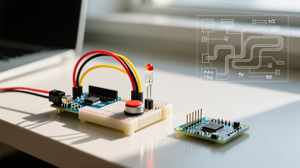
Wiring Topology: Connect one leg of the Omron switch to the 5V rail. Connect the opposite leg to Digital Pin 2. Wire the 10kΩ pull-down resistor between Digital Pin 2 and GND. For the output, wire Digital Pin 8 through the 330Ω resistor to the anode (long leg) of the LED, with the cathode connected to GND. We intentionally avoid Pin 13 for the LED, as the onboard SPI bootloader can cause Pin 13 to glitch during power-up, which is a common edge case that confuses beginners.
The Invisible Enemy: Contact Bounce Explained
When you press a mechanical switch, the metallic contacts (often made of beryllium copper or phosphor bronze) do not simply snap together and settle. Due to the kinetic energy of the actuator and the elasticity of the metal, the contacts physically bounce off one another multiple times before coming to rest. This phenomenon, known as 'contact bounce,' generates a rapid series of electrical pulses lasting anywhere from 1 millisecond to 50 milliseconds.
To a human, a single button press feels instantaneous. To a microcontroller executing millions of instructions per second, a single press looks like 15 to 30 rapid, distinct button presses. If your code toggles an LED on every LOW to HIGH transition, contact bounce will result in the LED ending up in a random state (either ON or OFF) depending on the exact microsecond the bouncing stops.
Debouncing Strategies: Hardware vs. Software
Engineers use two primary methods to filter out this noise. The official Arduino Debounce Documentation provides a baseline software approach, but understanding the trade-offs is critical for system design.
| Method | Implementation | Pros | Cons |
|---|---|---|---|
| Hardware RC Filter | 10kΩ resistor + 100nF capacitor + Schmitt Trigger | Zero CPU overhead; perfectly clean digital edge. | Increases BOM cost; consumes PCB space; introduces slight propagation delay. |
| Software Polling (Delay) | delay(50) after state change |
Trivial to write; requires no extra components. | Blocks the main loop; ruins timing for other tasks (e.g., motor control, audio). |
| Software Polling (millis) | Track time via millis() state machine |
Non-blocking; highly reliable; zero BOM cost. | Requires more complex code structure and state tracking. |
Writing Production-Grade Firmware
The most critical mistake in beginner button LED Arduino code is using Level Detection instead of State-Change Detection. If you simply write if (digitalRead(2) == HIGH) { toggleLED(); }, the LED will toggle thousands of times while the user holds the button down. We must detect the exact edge—the moment the pin transitions from LOW to HIGH.
Below is a robust, non-blocking implementation using millis() for debouncing and edge detection for accurate toggling.
// Pin Assignments
const int BUTTON_PIN = 2;
const int LED_PIN = 8;

// State Variables
int ledState = LOW;
int lastButtonState = LOW;
int currentButtonState = LOW;

// Timing Variables
unsigned long lastDebounceTime = 0;
const unsigned long debounceDelay = 50; // 50ms debounce window

void setup() {
  pinMode(BUTTON_PIN, INPUT);
  pinMode(LED_PIN, OUTPUT);
  digitalWrite(LED_PIN, ledState);
}

void loop() {
  // Read the raw state of the switch
  int reading = digitalRead(BUTTON_PIN);

  // Check if the reading differs from the last recorded state
  // If it does, it might be noise (bounce), so reset the timer
  if (reading != lastButtonState) {
    lastDebounceTime = millis();
  }

  // If the state has been stable for longer than the debounceDelay
  if ((millis() - lastDebounceTime) > debounceDelay) {
    // If the stable state is different from the current confirmed state
    if (reading != currentButtonState) {
      currentButtonState = reading;

      // EDGE DETECTION: Only toggle on the LOW-to-HIGH transition
      if (currentButtonState == HIGH) {
        ledState = !ledState; // Invert LED state
      }
    }
  }

  // Update the physical LED output
  digitalWrite(LED_PIN, ledState);

  // Save the reading for the next loop iteration
  lastButtonState = reading;
}
Edge Cases and Real-World Troubleshooting
Even with perfect code, physical hardware introduces variables that simulation environments hide. Here are the most common failure modes encountered in the field and how to resolve them:
- The 'Phantom Press' on Long Wires: If your push button is mounted on a chassis and connected to the Arduino via 3 feet of unshielded wire, the wire will act as an antenna for 60Hz AC mains hum. Solution: Switch from a 10kΩ pull-down resistor to a 1kΩ resistor. This lowers the impedance of the line, requiring significantly more induced current to accidentally pull the pin above the 2.5V logic threshold.
- Inverted Logic Confusion: If you decide to use the internal
INPUT_PULLUPmode to save a resistor, your wiring changes. The switch now connects the pin directly to GND. This means the pin readsHIGHwhen unpressed, andLOWwhen pressed. You must invert your edge-detection logic to look for aHIGHtoLOWtransition. - Power Supply Sag: If you are driving multiple high-brightness LEDs alongside your logic, the sudden current draw can cause the 5V rail to sag below 4.5V. This can cause the ATmega328P brownout detector (BOD) to trigger, resetting the microcontroller every time you press the button and activate the load. Solution: Isolate high-current LED loads using a logic-level N-channel MOSFET (like the IRLZ44N) rather than sourcing current directly from the Arduino GPIO.
Conclusion
Mastering the button LED Arduino circuit is about more than just making a light blink. It requires a fundamental understanding of CMOS impedance, the mechanical realities of metallurgy in switches, and the discipline to write non-blocking, edge-detected firmware. By implementing proper pull-down resistors and utilizing a millis()-based state machine, you transform a fragile breadboard toy into a resilient, production-ready input system.