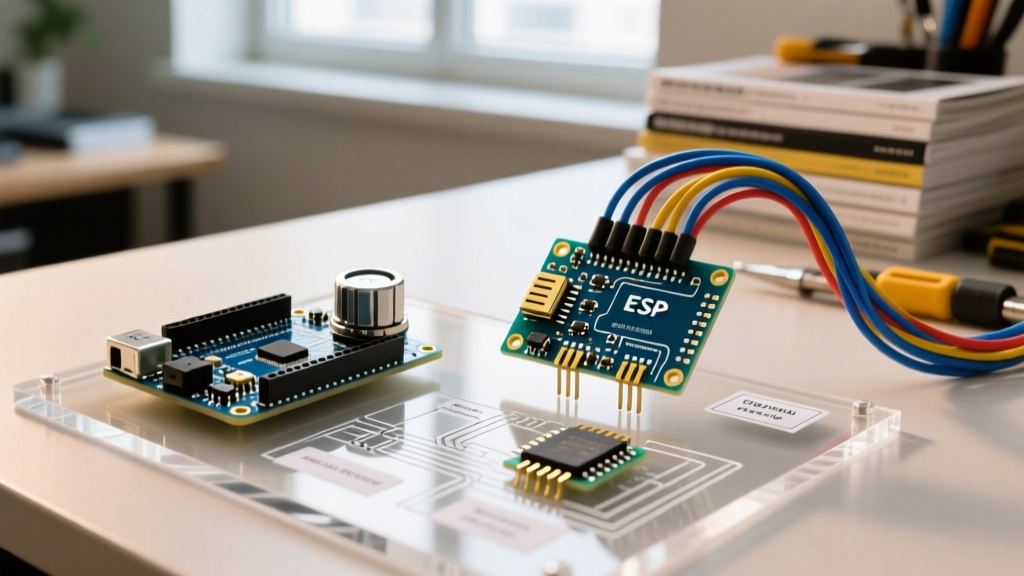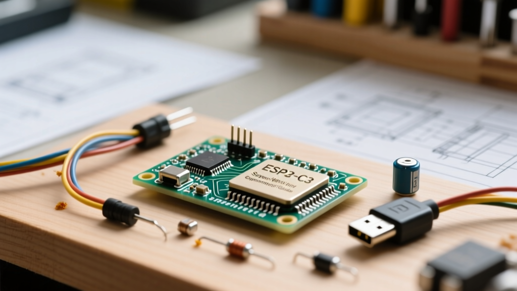

The ESP32-C3 Super Mini has rapidly become a staple in the maker community, offering a staggering price-to-performance ratio. Typically retailing between $2.50 and $3.80 on platforms like AliExpress, this tiny development board packs a RISC-V processor, Wi-Fi 4, and Bluetooth 5 into a footprint measuring roughly 0.9 by 1.3 inches. However, its ultra-compact size and unique architecture introduce several compatibility traps for makers transitioning from traditional AVR or Xtensa-based boards. This guide breaks down the exact hardware, software, and peripheral compatibility realities of the ESP32-C3 Super Mini.
Silicon Architecture: What You Are Actually Working With
Unlike the original ESP32 which utilizes a dual-core Xtensa LX6 32-bit processor, the Super Mini is built around the ESP32-C3FH4 SoC. This is a single-core 32-bit RISC-V microcontroller clocked at 160 MHz. It features 400 KB of SRAM and 4 MB of embedded SPI flash. Understanding this RISC-V architecture is critical for compatibility, as many older Arduino libraries hardcoded for Xtensa instruction sets or dual-core FreeRTOS tasks will fail to compile or behave unpredictably. Furthermore, the C3 lacks the capacitive touch sensors found on its predecessors, meaning any project relying on the touchRead() function will immediately throw compilation errors.
IDE and Firmware Ecosystem Compatibility
Getting the Arduino IDE to recognize the ESP32-C3 Super Mini requires specific toolchain configurations. Because it uses a RISC-V core, you must use the official Espressif board definitions.
- Board Manager URL: Add the Arduino ESP32 Core Repository URL to your IDE preferences.
- Core Version: Use version 2.0.14 or the newer 3.x branch. Earlier 1.x versions lack stable RISC-V support.
- Board Selection: Select "ESP32C3 Dev Module". Do not select the standard "ESP32 Dev Module".
- USB CDC On Boot: Must be set to Enabled if you are using the onboard USB-C port for serial debugging.
- Flash Mode: QIO (Quad I/O) is recommended for optimal read speeds from the 4MB flash.
For MicroPython users, the board is fully compatible with the generic ESP32-C3 firmware builds provided by the MicroPython project, though you must use the USB-CDC specific builds rather than the UART-specific builds to utilize the native USB port.
The D1 Mini Footprint Trap: Shield Compatibility Constraints
One of the most common mistakes makers make is assuming the ESP32-C3 Super Mini is a drop-in replacement for the Wemos D1 Mini (ESP8266). While the physical dimensions and 8-pin header spacing are nearly identical, the pinout mapping is entirely different.
D1 Mini shields designed for I2C, OLED displays, or motor drivers will not work out-of-the-box. On the D1 Mini, D1 is GPIO5 (SCL) and D2 is GPIO4 (SDA). On the ESP32-C3 Super Mini, the pins labeled on the silk screen correspond to raw GPIO numbers, and the default I2C pins are typically mapped to GPIO4 (SDA) and GPIO5 (SCL), but physical board layouts vary wildly between manufacturers (e.g., VCC-GND Studio vs. generic clones). Always verify the specific silk screen mapping against the Espressif ESP32-C3 Datasheet before soldering shields.
Power Delivery Realities and LDO Thermal Limits
The ESP32-C3 Super Mini features a USB-C connector, but it is vital to understand its power delivery limitations. The board utilizes a small SOT-23-5 package Low Dropout Regulator (LDO), frequently the ME6211C33 or a similar clone, to step down the 5V USB input to 3.3V.
While the ME6211 is theoretically rated for 500mA, the tiny PCB footprint lacks the copper pour necessary for adequate heat dissipation. Pushing the onboard LDO past 250mA to 300mA will cause thermal throttling and voltage sag.
If your project involves driving WS2812B NeoPixel strips, high-draw servos, or dense sensor arrays, you must bypass the onboard LDO. Power the 5V rail externally and use a dedicated, high-efficiency buck converter to feed the 3.3V pin directly. Furthermore, the ESP32-C3 is strictly a 3.3V logic device. It is not 5V tolerant. Connecting a 5V I2C or SPI sensor directly to the GPIO pins will permanently destroy the SoC's input buffers.
Strapping Pin Conflicts and Bootloader Failures
The ESP32-C3 relies on specific strapping pins to determine boot modes. If external circuits interfere with these pins during power-on or reset, the Super Mini will fail to boot or enter an endless reset loop.
| GPIO Pin | Function | Boot Requirement | Common Failure Mode |
|---|---|---|---|
| GPIO8 | TXD / Log Print | Must be HIGH for normal boot log | Pulled low by external UART devices |
| GPIO9 | BOOT Mode | Must be HIGH for SPI Flash Boot | Pulled low by external buttons/sensors |
GPIO9 is the most notorious culprit. On the Super Mini, GPIO9 is often broken out and used as a standard digital input. If you wire a pull-down resistor or a switch that grounds GPIO9, the chip will enter the serial bootloader on every reset and will not execute your sketch. Always use 10kΩ pull-up resistors on GPIO9 if it must be used for peripheral interfacing.
Analog-to-Digital Converter (ADC) and Sensor Interfacing
Compatibility with analog sensors is another area requiring careful navigation. The ESP32-C3 features only ADC1, with channels mapped to GPIO0 through GPIO4. Unlike the ESP32-S3 or the original ESP32, the C3's ADC is notoriously non-linear and suffers from significant internal noise.
When interfacing with precision analog sensors like the MQ-135 gas sensor or standard potentiometers, you must implement software oversampling (reading the pin 16 to 64 times and averaging the result) and apply a multi-point calibration curve in your code. Relying on a single analogRead() call will yield erratic data. Additionally, the ADC input range is strictly 0V to 2.5V on most C3 silicon revisions, not 3.3V. Feeding 3.3V into an ADC pin will result in saturation and inaccurate maximum readings.
Troubleshooting Native USB and Upload Failures
The ESP32-C3 Super Mini utilizes native USB via GPIO18 (D-) and GPIO19 (D+), eliminating the need for a dedicated CP2102 or CH340 UART bridge chip. While this saves space and cost, it introduces a specific failure mode: USB CDC dropping during deep sleep.
When the microcontroller enters deep sleep, the USB peripheral is powered down. Upon waking, the host operating system (Windows/Linux/macOS) often fails to re-enumerate the COM port fast enough, causing the Arduino IDE serial monitor to hang or the upload process to fail with a "Failed to connect to ESP32" error.
The Manual Bootloader Override:
If the IDE fails to initiate the download mode automatically, you must manually force the bootloader. Because the Super Mini usually only features a single "RST" button and lacks a dedicated "BOOT" button, you must use the following sequence:
- Press and hold the onboard RST button.
- While holding RST, briefly touch a jumper wire from GND to GPIO9 (the BOOT strapping pin).
- Release the RST button.
- Remove the jumper wire from GPIO9.
- Click "Upload" in the Arduino IDE.
By mastering these hardware quirks, power constraints, and pinout realities, you can effectively integrate the ESP32-C3 Super Mini into robust, production-ready IoT and maker projects without falling victim to its common compatibility traps.