
The 'Cheap Yellow Display' Hardware Anatomy
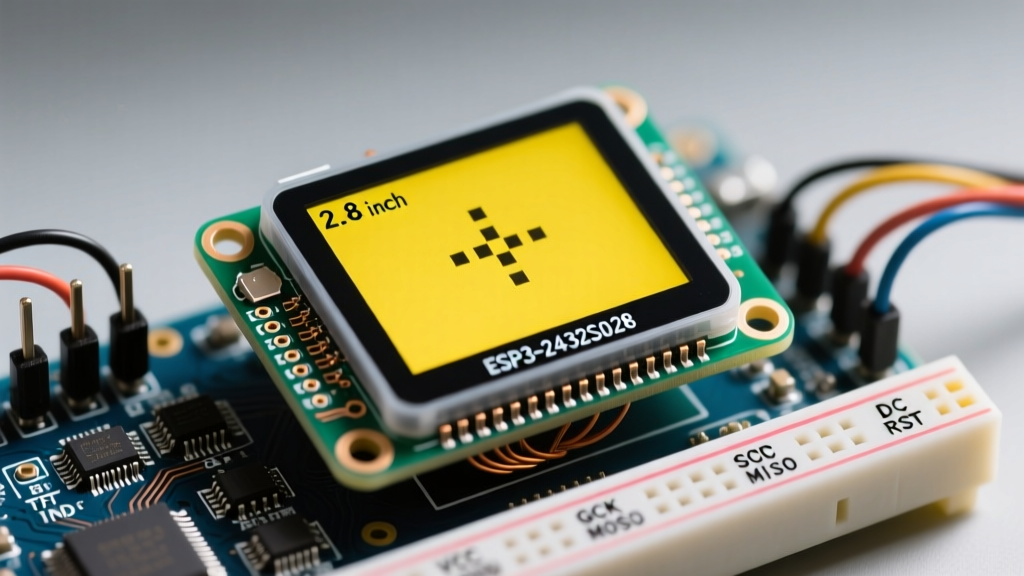
The ESP32-2432S028, affectionately dubbed the 'Cheap Yellow Display' (CYD) by the maker community, has become a staple for DIY smart home dashboards, weather stations, and industrial HMIs. Priced aggressively, it integrates an ESP32-WROOM-32 microcontroller with a 2.8-inch 320x240 ILI9341 TFT LCD and an XPT2046 resistive touch overlay. However, its aggressive cost-cutting leads to a highly unconventional pinout architecture that routinely traps beginners in compilation errors and blank screens.
Unlike standard development boards where the display and touch controllers share a single SPI bus, the ESP32-2432S028 routes them through entirely separate hardware SPI channels. Understanding this dual-bus architecture is the single most critical step in configuring this board.
Core Component Breakdown
| Component | Model / Spec | Interface | Primary Function |
|---|---|---|---|
| Microcontroller | ESP32-WROOM-32 (4MB Flash) | N/A | Core processing, Wi-Fi, Bluetooth |
| Display Controller | ILI9341 (2.8", 320x240) | VSPI (Hardware) | TFT pixel rendering |
| Touch Controller | XPT2046 | HSPI (Hardware) | Resistive touch coordinate mapping |
| USB-to-UART | CH340C or CP2102 | USB | Serial programming and power |
| Ambient Light Sensor | GL5528 LDR | ADC (GPIO 34) | Auto-brightness adjustment |
Arduino IDE Board & Environment Configuration
Before writing a single line of code, your Arduino IDE environment must be configured to handle the ESP32's specific memory layout. The ESP32-2432S028 typically ships with a 4MB flash module and no PSRAM. Selecting a board profile with PSRAM enabled will cause immediate boot-loops or memory allocation faults.
- Board Manager: Install the 'esp32' board package by Espressif Systems (version 2.0.x or 3.0.x).
- Board Selection: Choose ESP32 Dev Module.
- Flash Size: Set to 4MB (32Mb).
- PSRAM: Set to Disabled.
- Flash Mode: Set to DIO (Dual I/O is standard for these clone boards).
- Upload Speed: 921600 (or drop to 460800 if you experience CH340C timeout errors).
Pro-Tip: If your board fails to enter download mode automatically, hold the 'BOOT' button on the PCB while clicking 'Upload' in the IDE, then release it once the console says 'Connecting...'.
TFT_eSPI Library: The User_Setup.h Masterclass
The TFT_eSPI library by Bodmer is the gold standard for driving ILI9341 displays on the ESP32. However, it requires manual configuration via the User_Setup.h file. This is where 90% of ESP32-2432S028 projects fail.
Locate the User_Setup.h file inside the TFT_eSPI library folder in your Arduino libraries directory. Comment out all default display drivers and uncomment the following specific definitions:
// 1. Display Driver Selection
// Some CYD batches use a slightly different ILI9341 clone.
// If ILI9341_DRIVER yields a white screen, switch to ILI9341_2_DRIVER.
#define ILI9341_DRIVER

// 2. Resolution
#define TFT_WIDTH  240
#define TFT_HEIGHT 320

// 3. ESP32-2432S028 Display SPI Pin Mapping (VSPI)
#define TFT_MISO 12
#define TFT_MOSI 13
#define TFT_SCLK 14
#define TFT_CS   15  // Chip select control pin
#define TFT_DC    2  // Data Command control pin
#define TFT_RST  -1  // Reset pin (tied to EN on this board)
#define TFT_BL   21  // LED back-light control pin

// 4. SPI Frequency
#define SPI_FREQUENCY  40000000 // 40MHz is stable; 55MHz may cause artifacts
The Touch Controller Trap: Do NOT Define TOUCH_CS Here
In standard TFT_eSPI configurations, you define TOUCH_CS in the User_Setup.h file to enable touch. Do not do this for the ESP32-2432S028. Because the CYD routes the touch controller to a separate SPI bus, defining it here forces the library to poll the touch chip on the display's SPI bus, resulting in bus contention, fatal exceptions, or completely unresponsive touch inputs.
XPT2046 Touch Controller Integration via Dual SPI
To read touch inputs, we must instantiate a secondary hardware SPI bus. The XPT2046 chip on the CYD is wired to the HSPI bus with the following pins: SCK=25, MISO=39, MOSI=32, CS=33, and IRQ=36.
We utilize the XPT2046_Touchscreen library by Paul Stoffregen to handle the secondary bus. Below is the robust initialization pattern required to get both the display and touch operating simultaneously without SPI collisions.
#include <SPI.h>
#include <TFT_eSPI.h>
#include <XPT2046_Touchscreen.h>

// Touch Pin Definitions
#define TOUCH_CS  33
#define TOUCH_IRQ 36

// Instantiate a separate SPI class for the Touch Controller (HSPI)
SPIClass touchscreenSPI = SPIClass(HSPI);
XPT2046_Touchscreen touchscreen(TOUCH_CS, TOUCH_IRQ);

TFT_eSPI tft = TFT_eSPI();

void setup() {
  Serial.begin(115200);

  // Initialize Display (TFT_eSPI handles VSPI automatically)
  tft.init();
  tft.setRotation(1); // Landscape mode
  tft.fillScreen(TFT_BLACK);
  tft.setTextColor(TFT_WHITE, TFT_BLACK);
  tft.setTextSize(2);
  tft.println('CYD Dual-SPI Ready');

  // Initialize Touch on HSPI
  touchscreenSPI.begin(25, 39, 32, 33); // SCK, MISO, MOSI, SS
  touchscreen.begin(touchscreenSPI);
  touchscreen.setRotation(1); // Match display rotation
}

void loop() {
  if (touchscreen.tirqTouched() && touchscreen.touched()) {
    TS_Point p = touchscreen.getPoint();
    // Map raw touch data to 320x240 screen coordinates
    int x = map(p.x, 200, 3700, 0, 320);
    int y = map(p.y, 240, 3800, 0, 240);
    Serial.printf('Touch X: %d, Y: %d\n', x, y);
  }
}
Peripheral Pinout Map: Beyond the Screen
The ESP32-2432S028 PCB includes several onboard peripherals that makers often overlook. Referencing Brian Lough's definitive CYD documentation, here is the exact mapping for the secondary features:
- RGB LED: Red = GPIO 4, Green = GPIO 16, Blue = GPIO 17. Note: These are Active LOW. Writing HIGH turns them off.
- Light Dependent Resistor (LDR): GPIO 34. Use
analogRead(34)to read ambient light levels (0-4095) and dynamically adjust the backlight PWM on GPIO 21. - Speaker / Buzzer: GPIO 26. Capable of basic PWM tone generation via the ESP32 LEDC API.
- MicroSD Card Slot: CS = GPIO 5. Warning: The SD card shares the same VSPI bus as the TFT display. You must manage chip select states carefully to avoid data corruption.
Troubleshooting Common CYD Failures
1. The 'White Screen of Death'
If your backlight turns on but the screen is solid white, your SPI communication is failing. First, verify your User_Setup.h pinout. Second, swap #define ILI9341_DRIVER to #define ILI9341_2_DRIVER. Manufacturers frequently substitute the ILI9341 with pin-compatible clones that require the alternate initialization sequence provided by the '_2' driver macro.
2. Touch Inputs are Inverted or Offset
Resistive touch screens require physical calibration. If your X and Y axes are swapped or inverted, do not alter the wiring. Instead, adjust the map() function multipliers in the loop. Furthermore, ensure touchscreen.setRotation(1) matches your tft.setRotation(1). The XPT2046 chip has its own independent rotation matrix that must be explicitly synced to the TFT_eSPI canvas.
3. Backlight Flickering or Dimming
GPIO 21 controls the backlight. If you are using ledcWrite() for PWM brightness control, ensure you are using a frequency of at least 1000Hz. Lower frequencies will cause visible flickering on camera sensors and to the human eye. Additionally, the linear regulator on the CYD PCB can overheat if the backlight is driven at 100% duty cycle while simultaneously powering Wi-Fi and external sensors. Limit max brightness to 80% for thermal stability.
Final Thoughts on ESP32-2432S028 Deployment
The ESP32-2432S028 offers an unmatched price-to-performance ratio for embedded UI projects, provided you respect its hardware quirks. By treating the display and touch controllers as entirely separate SPI entities and properly configuring the TFT_eSPI library, you transform this budget board into a highly responsive, production-ready HMI platform. Always double-check your User_Setup.h against the physical silkscreen on your specific PCB revision, as clone manufacturers occasionally shift pin assignments between production runs.