
The "Fake" Analog Output Problem on Classic MCUs
For years, the standard Arduino analog output tutorial has relied on the analogWrite() function. However, veteran makers and engineers know a fundamental truth: the classic ATmega328P (found on the Arduino Uno R3 and Nano) does not have a true Digital-to-Analog Converter (DAC). Instead, it uses Pulse Width Modulation (PWM) to simulate analog voltages by rapidly switching a 5V digital pin on and off.
While PWM is perfectly adequate for dimming LEDs or controlling the average speed of a DC motor via an H-bridge, it fails catastrophically in applications requiring smooth, continuous voltage. If you are building audio synthesizers, precision lab instruments, or analog control loops for PID systems, the 490 Hz (or 980 Hz on pins 5 and 6) square wave ripple of PWM will introduce massive noise and instability.
This migration guide outlines how to upgrade your projects from simulated PWM to true analog voltage outputs using modern native MCUs and external DAC modules.
Migration Path 1: The Modern Native Upgrade
If your project is constrained by the ATmega328P's lack of a DAC, the most seamless migration path is upgrading to a microcontroller with native DAC hardware. As of 2026, the ecosystem offers several robust options.
Arduino Uno R4 (Renesas RA4M1)
The most significant disruption to the classic Arduino form factor is the Uno R4 (available in Minima at ~$27.50 and WiFi at ~$35.00). Powered by the 32-bit ARM Cortex-M4 Renesas RA4M1, the Uno R4 includes a true 12-bit DAC hardwired to pin A0.
- Resolution: 12-bit (0 to 4095 discrete steps).
- Logic Level: 3.3V (Requires level shifting if driving 5V logic).
- Migration Step: Change
analogWrite(pin, value)toanalogWrite(A0, value)and ensure your code scales the 8-bit PWM range (0-255) to the 12-bit DAC range (0-4095) by multiplying by 16.
Arduino Due (SAM3X8E) & Zero (SAMD21)
For legacy 32-bit projects, the Arduino Due offers dual 12-bit DACs on pins DAC0 and DAC1, capable of sourcing up to 3mA. The Arduino Zero offers a single 10-bit DAC on pin A0. Both operate at 3.3V logic and are ideal for dual-channel waveform generation or stereo audio synthesis.
Migration Path 2: External I2C DAC Integration (MCP4725)
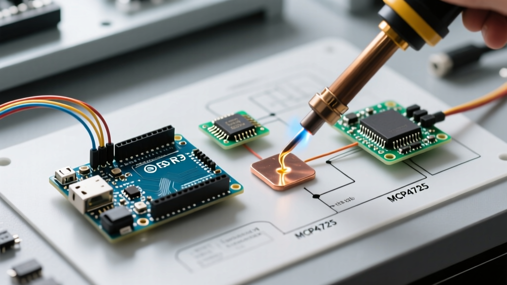
If you cannot replace your classic Uno R3 or Nano due to legacy shield compatibility or strict BOM constraints, adding an external DAC via I2C is the industry-standard workaround. The Microchip MCP4725 is the undisputed workhorse for this migration.
Expert Note: The MCP4725 breakout board typically costs between $6.00 and $9.00 in 2026. It features an onboard EEPROM, meaning it can remember its last analog output state during a power cycle—a critical feature for motorized valve positioning and calibration equipment.
Wiring and I2C Address Configuration
The MCP4725 communicates via I2C, requiring only four connections to your Arduino:
| MCP4725 Pin | Arduino Uno R3 Pin | Function |
|---|---|---|
| VDD | 5V | Power supply (Sets max analog output to 5V) |
| GND | GND | Common ground reference |
| SCL | A5 | I2C Clock |
| SDA | A4 | I2C Data |
Note: The default I2C address is 0x62. Pulling the A0 address pin to VDD shifts the address to 0x63, allowing two modules on the same bus.
Code Migration: Translating Sketches for True Analog
Migrating your sketch from PWM to an I2C DAC requires replacing the hardware-timed analogWrite() with I2C bus transactions. Below is the optimized migration pattern using the Adafruit MCP4725 library.
#include <Wire.h>
#include <Adafruit_MCP4725.h>

Adafruit_MCP4725 dac;

void setup() {
  Serial.begin(115200);
  // Initialize DAC at I2C address 0x62
  dac.begin(0x62);
}

void loop() {
  // Generate a precise 2.5V output on a 5V VDD reference
  // 4095 * (2.5 / 5.0) = 2047
  dac.setVoltage(2047, false);
  delay(1000);

  // Generate a 0V to 5V sawtooth wave
  for (uint16_t i = 0; i < 4096; i++) {
    dac.setVoltage(i, false);
  }
}
Hardware Comparison Matrix (2026)
When planning your analog output upgrade, use this matrix to select the right architecture for your specific engineering constraints.
| Feature | ATmega328P (PWM) | Uno R4 (Native DAC) | MCP4725 (External DAC) |
|---|---|---|---|
| Output Type | Square Wave (Duty Cycle) | True Continuous Voltage | True Continuous Voltage |
| Resolution | 8-bit (256 steps) | 12-bit (4096 steps) | 12-bit (4096 steps) |
| Max Frequency | ~980 Hz (Pins 5,6) | Up to 120 kHz (approx) | ~200 Hz (I2C Bus Limited) |
| Logic Level | 5V | 3.3V | Depends on VDD (3.3V or 5V) |
| Best Use Case | LED Dimming, Motor Speed | Audio, Waveform Gen | Programmable Power Supplies, Calibration |
Critical Edge Cases: Output Impedance and Buffering
The most common failure mode when migrating to true DACs is loading the output. Unlike digital pins that can source 20mA to 40mA, native MCU DACs and the MCP4725 have high output impedances and low current sourcing capabilities (typically 2mA to 5mA).
The Buffering Solution
If your true analog output needs to drive a low-impedance load (like an 8-ohm speaker, a 50-ohm coaxial cable, or a heavy capacitive load), the voltage will sag, and the DAC may oscillate or suffer permanent thermal damage.
- For Audio/Low Power: Use a rail-to-rail CMOS op-amp like the MCP6001 or LMV321 configured as a unity-gain voltage follower. This drops the output impedance to fractions of an ohm while preserving the exact DAC voltage.
- For Power Control: If you are using the DAC to set a reference voltage for a high-current power supply, buffer it with an LM358 (for single-supply 5V systems) or a power op-amp like the L298N logic stage.
The Middle Ground: RC Low-Pass Filtering for PWM
If you are strictly locked into an ATmega328P Nano and cannot add an I2C DAC due to pin constraints, you can convert PWM to a quasi-analog DC voltage using a passive RC Low-Pass Filter. By placing a 10kΩ resistor in series with the PWM pin, followed by a 100nF ceramic capacitor to ground, you create a filter with a cutoff frequency of roughly 160 Hz. This smooths the 490 Hz PWM ripple into a relatively flat DC voltage. However, be aware that the response time to voltage changes will be severely limited (taking milliseconds to settle), making this unsuitable for real-time control loops.
Summary
Upgrading your Arduino analog output from basic PWM to a true DAC is a mandatory step for any project transitioning from hobbyist prototyping to precision instrumentation. Whether you leverage the native 12-bit DAC on the modern Arduino Uno R4, utilize the dual DACs of the Arduino Due, or integrate an external MCP4725 via I2C, understanding the trade-offs in resolution, logic levels, and output impedance will ensure your signals remain clean, stable, and highly accurate.