
The Core Concept: Polling vs. Hardware Interrupts
In microcontroller programming, reading a sensor or button using digitalRead() inside the loop() is known as polling. While simple, polling is inherently inefficient. If your main loop is busy driving a display or executing complex math, it might miss a fleeting 5-millisecond button press. This is where the Arduino attachInterrupt function becomes indispensable.
Hardware interrupts allow external events to immediately pause the main program, execute a specific block of code called an Interrupt Service Routine (ISR), and then seamlessly resume the main loop. Whether you are decoding a high-speed rotary encoder, capturing anemometer wind speed pulses, or building an emergency hardware kill-switch, mastering attachInterrupt() is a mandatory skill for any serious maker or embedded engineer.
Anatomy of the Arduino attachInterrupt Function
The standard syntax for the function is:
attachInterrupt(digitalPinToInterrupt(pin), ISR, mode);Let us break down these three parameters with engineering precision:
- digitalPinToInterrupt(pin): Never pass a raw integer like
2directly into the first parameter unless you are using legacy AVR-specific vector numbers. ThedigitalPinToInterrupt()macro translates the physical silk-screened GPIO pin number on your board into the correct internal hardware interrupt vector. This ensures your code remains portable across different architectures. - ISR (Interrupt Service Routine): The name of the function to call. This function must take no parameters and return nothing (
void). - mode: Defines the electrical trigger condition.
LOW: Triggers continuously while the pin is low (rarely used, causes ISR flooding).CHANGE: Triggers on both rising and falling edges (ideal for quadrature encoders).RISING: Triggers when the pin goes from LOW to HIGH.FALLING: Triggers when the pin goes from HIGH to LOW (ideal for active-low buttons).
Microcontroller Interrupt Pin Mapping (2026 Reference)
Not all pins support hardware interrupts. The ATmega328P is highly restricted, while modern ESP32 variants utilize a flexible GPIO matrix. Below is a reference table for the most common development boards used in 2026.
| Board / Architecture | Microcontroller | Usable Interrupt Pins | Hardware Notes |
|---|---|---|---|
| Uno / Nano / Pro Mini | ATmega328P (8-bit AVR) | 2, 3 | Maps to INT0 and INT1 vectors. |
| Mega2560 | ATmega2560 (8-bit AVR) | 2, 3, 18, 19, 20, 21 | Supports up to 6 simultaneous external interrupts. |
| Leonardo / Micro | ATmega32U4 (8-bit AVR) | 0, 1, 2, 3, 7 | Pin 7 uses a different interrupt vector (INT6). |
| ESP32 DevKit V1 / S3 | ESP32 / ESP32-S3 (Xtensa) | All GPIOs except 6-11 | GPIOs 6-11 are tied to the internal SPI flash. Do not use. |
Source: Consult the official Arduino Language Reference for architecture-specific edge cases.
Step-by-Step Implementation: Building a Debounced Interrupt Circuit
Switch bounce is the nemesis of hardware interrupts. A standard tactile switch will mechanically bounce for 1 to 5 milliseconds, generating dozens of false interrupt triggers. While software debouncing (using millis() inside the ISR) is possible, hardware debouncing is vastly superior for preserving CPU cycles.
Step 1: Hardware Wiring and Component Selection
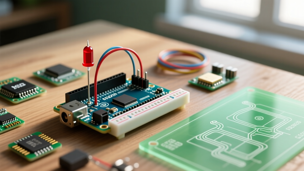
For a reliable FALLING edge interrupt circuit, you need:
- 10kΩ Pull-up Resistor: Connects between the GPIO pin and VCC (5V or 3.3V). Keeps the line HIGH when the switch is open. (Cost: ~$0.01 per unit).
- Tactile Switch: Connects between the GPIO pin and GND.
- 100nF (0.1µF) Ceramic Capacitor: Placed in parallel with the switch (between GPIO and GND). This creates an RC low-pass filter that absorbs the mechanical bounce before it reaches the silicon threshold.
Step 2: Writing the ISR and Main Loop
Variables shared between the ISR and the main loop must be declared with the volatile keyword. This instructs the GCC compiler to fetch the variable from RAM every time, preventing aggressive optimization from caching it in a CPU register.
const byte interruptPin = 2;
volatile unsigned long pressCount = 0;
unsigned long lastReport = 0;

void setup() {
  pinMode(interruptPin, INPUT); // External 10k pull-up used
  Serial.begin(115200);
  attachInterrupt(digitalPinToInterrupt(interruptPin), buttonISR, FALLING);
}

void buttonISR() {
  pressCount++;
}

void loop() {
  if (millis() - lastReport >= 1000) {
    noInterrupts(); // Critical section start
    unsigned long safeCount = pressCount;
    interrupts();   // Critical section end

    Serial.print("Presses this second: ");
    Serial.println(safeCount);
    lastReport = millis();
  }
}
Critical Edge Cases and Memory Pitfalls
Even experienced developers fall into ISR traps. Here are the advanced failure modes you must design around.
The 8-Bit Race Condition
Notice the noInterrupts() and interrupts() block in the code above? On an 8-bit ATmega328P, reading a 16-bit or 32-bit volatile variable takes multiple clock cycles. If an interrupt fires exactly between the reading of the lower byte and the upper byte, your main loop will read a corrupted, hybrid value. Always disable interrupts momentarily when copying multi-byte volatile variables into local scope.
The Serial.print() Deadlock
The Golden Rule of ISRs: Never use
Serial.print(),delay(), ormillis()inside an Interrupt Service Routine. Doing so will crash or hang your microcontroller.
As detailed in Nick Gammon's definitive guide on interrupts, the Arduino Serial library relies on background interrupts to empty its TX buffer. If you call Serial.print() from within an ISR (where global interrupts are automatically disabled), the serial buffer will fill up and block indefinitely, causing a hard system lockup.
Clearing the EIFR Register
If you temporarily disable an interrupt using detachInterrupt() or noInterrupts(), the hardware flag may still be set if a trigger occurred during the blind period. When you re-enable the interrupt, the ISR will fire immediately with stale data. On AVR boards, you must manually clear the External Interrupt Flag Register (EIFR) before re-enabling:
EIFR = bit(INTF0); // Clears the flag for INT0 (Pin 2 on Uno)Real-World Application: Quadrature Rotary Encoders
Rotary encoders output two square waves (Phase A and Phase B) offset by 90 degrees. To track rotation accurately at high speeds (e.g., 2000 RPM on a CNC jog wheel), polling is too slow. By attaching an interrupt to Phase A using the CHANGE mode, you can read the state of Phase B inside the ISR to determine direction. Modern ESP32-S3 boards (typically priced around $7-$9 in 2026) feature a dedicated Pulse Counter (PCNT) hardware peripheral that handles this without CPU intervention, but for ATmega-based boards, attachInterrupt() remains the standard approach. For ESP32 specific GPIO routing, refer to the Espressif Arduino Core GPIO documentation.
Frequently Asked Questions
Why is my ISR triggering randomly without a button press?
You have a floating pin. If you did not wire an external pull-up resistor, you must enable the internal one using pinMode(pin, INPUT_PULLUP);. Electromagnetic interference (EMI) from nearby motors or relays will easily induce false triggers on high-impedance floating lines.
Can I use I2C or SPI devices inside an ISR?
No. I2C and SPI transactions take milliseconds to complete and rely on hardware state machines that can be disrupted by the interrupt context. Set a volatile boolean flag inside the ISR, and handle the I2C/SPI communication in the main loop() based on that flag.
How long can an ISR run?
As short as possible. An ISR should ideally execute in under 5 microseconds. If your ISR takes too long, you will drop subsequent interrupts, miss incoming serial data, and disrupt the millis() timer, which relies on the Timer0 overflow interrupt to keep time.