
The Voltage Trap: 5V ATmega vs 3.3V Broadcom/RP1 Logic
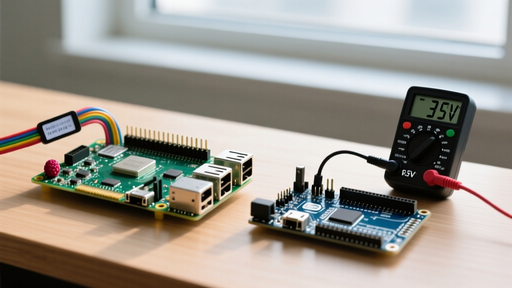
When makers decide to upgrade from an Arduino Uno to a Raspberry Pi for edge computing, computer vision, or advanced IoT networking, the physical migration of the Raspberry Pi GPIO header is often where projects meet their demise. The fundamental hurdle is logic voltage. The ubiquitous Arduino Uno (based on the ATmega328P) operates at 5V logic. In stark contrast, the Raspberry Pi 4 (BCM2711 SoC) and the newer Raspberry Pi 5 (RP1 I/O controller) operate strictly at 3.3V logic.
Feeding a 5V signal from an Arduino sensor or a 5V relay module directly into a Raspberry Pi GPIO pin will bypass the internal protection diodes, permanently damaging the silicon. To safely migrate 5V peripherals, you must implement bidirectional logic level shifters. The Texas Instruments TXS0108E or SparkFun's BSS138-based MOSFET level shifters are industry standards for this translation. Furthermore, be mindful of internal pull-up resistors: the ATmega328P uses ~20kΩ internal pull-ups, while the Raspberry Pi uses ~50kΩ. This discrepancy can alter RC timing circuits and I2C bus rise times during migration, often requiring external 4.7kΩ pull-up resistors on I2C lines that previously worked fine on the Arduino.
Mapping the Pins: Arduino UNO to Raspberry Pi 40-Pin Header
Unlike the Arduino's silkscreened digital and analog pins, the Raspberry Pi 40-pin header is a mix of power rails, grounds, and multiplexed GPIOs. Below is a practical translation map for migrating common Arduino Uno peripherals to the Raspberry Pi GPIO header.
| Arduino UNO Pin | Typical Function | Raspberry Pi Equivalent (BCM) | Migration Notes & Warnings |
|---|---|---|---|
| D2 (INT0) | Hardware Interrupt | GPIO 17 (Pin 11) | Use gpiozero interrupt callbacks; avoid polling. |
| D3 (PWM) | Servo / Motor PWM | GPIO 18 (Pin 12) | GPIO 18 is the primary hardware PWM0 pin on Pi 4/5. |
| D13 (SCK) | SPI Clock | GPIO 11 / SPI0_SCLK (Pin 23) | Pi SPI bus runs at 3.3V. Level shift if connecting to 5V shields. |
| A4 (SDA) | I2C Data | GPIO 2 / I2C1_SDA (Pin 3) | Requires 4.7kΩ pull-ups to 3.3V. Do not use 5V pull-ups. |
| A0 - A5 | Analog Input (ADC) | N/A (No native ADC) | Must add an external ADC like the ADS1115 (I2C) or MCP3008 (SPI). |
| 5V Pin | Power Out/In | 5V Rail (Pins 2 & 4) | Pi 5 requires high-amperage USB-C PD; do not backpower via GPIO. |
The Pi 5 Paradigm Shift: Enter the RP1 Chip
If you are upgrading specifically to the Raspberry Pi 5, you must understand a massive architectural shift in the Raspberry Pi GPIO subsystem. Previous Pi models routed GPIO directly through the main Broadcom SoC. The Raspberry Pi 5 offloads all I/O operations to a custom southbridge chip called the RP1.
Critical Warning: The legacy
RPi.GPIOPython library relies on direct memory access (/dev/mem) to the Broadcom SoC registers. Because the RP1 chip handles GPIO on the Pi 5 via a PCIe interface,RPi.GPIOis fundamentally incompatible and largely deprecated. Makers migrating in 2024 and beyond must adoptgpiozero(which utilizes thelgpiobackend on Pi 5) or the C-basedlibgpiodlibrary.
This transition means old Python scripts using import RPi.GPIO as GPIO will throw runtime errors on a Pi 5. You must refactor your codebase to use object-oriented gpiozero classes or interact with the Linux kernel's standard GPIO character device (/dev/gpiochip).
Software Translation: C++ Sketches to Python GPIO Zero
Migrating from Arduino's C++ environment to Raspberry Pi's Python ecosystem requires a shift from procedural setup/loop paradigms to event-driven or object-oriented scripting. The GPIO Zero Migration Guide highly recommends abstracting pins into physical components.
Arduino C++ Approach
// Arduino C++ Sketch
const int buttonPin = 2;
const int ledPin = 13;

void setup() {
  pinMode(buttonPin, INPUT_PULLUP);
  pinMode(ledPin, OUTPUT);
}

void loop() {
  if (digitalRead(buttonPin) == LOW) {
    digitalWrite(ledPin, HIGH);
  } else {
    digitalWrite(ledPin, LOW);
  }
}
Raspberry Pi Python Approach (gpiozero)
# Raspberry Pi Python Script
from gpiozero import LED, Button
from signal import pause

# BCM numbering is default in gpiozero
led = LED(13)
button = Button(2, pull_up=True)

# Event-driven callbacks replace the blocking loop()
button.when_pressed = led.on
button.when_released = led.off

pause() # Keeps the script alive to listen for events
This event-driven model is vastly superior for IoT applications, as it frees up the Pi's CPU to handle networking, camera streams, or database logging while waiting for hardware interrupts.
Solving the Analog and PWM Deficit
The most jarring realization when migrating to the Raspberry Pi GPIO header is the lack of native Analog-to-Digital Conversion (ADC) and the limitations of Pulse Width Modulation (PWM).
- Analog Inputs: The Arduino features a 10-bit ADC on pins A0-A5. The Pi has zero. To migrate analog sensors (like potentiometers, LDRs, or MQ gas sensors), you must integrate an external ADC. The ADS1115 (16-bit, I2C) is highly recommended for precision, while the MCP3008 (10-bit, SPI) is a drop-in replacement for Arduino's resolution.
- PWM Limitations: Arduino's
analogWrite()provides software PWM on almost all digital pins at ~490Hz. The Pi has only a few true hardware PWM pins (GPIO 18, 19, 12, 13) and its software PWM is notoriously jittery due to Linux kernel scheduling. For high-frequency or precise motor control migration, install the pigpio daemon, which utilizes DMA (Direct Memory Access) to generate rock-solid, jitter-free software PWM on any GPIO pin.
Real-World Migration Checklist
Before desoldering your Arduino and wiring up the Pi, run through this hardware and software checklist to ensure a seamless upgrade:
- Audit Voltage Levels: Identify every 5V sensor and actuator. Order BSS138 level shifters or optocouplers for high-voltage isolation.
- Verify I2C Addresses: Ensure your 3.3V I2C sensors do not conflict. The Pi's I2C bus can be sensitive to capacitance; keep wires under 30cm or add external pull-ups.
- Procure an External ADC: If your sketch uses
analogRead(), add an ADS1115 breakout board to your BOM. - Refactor to gpiozero: Rewrite your logic using Python's
gpiozerolibrary to ensure forward compatibility with the Pi 5's RP1 chip and future Raspberry Pi hardware architectures. - Implement Graceful Shutdowns: Unlike an Arduino, the Pi runs a full Linux OS. Add a physical push-button mapped to a shutdown script to prevent SD card corruption when cutting power.
Migrating from a microcontroller to a single-board computer unlocks immense processing power, but respecting the electrical and architectural boundaries of the Raspberry Pi GPIO header is the key to a successful, long-lasting project.