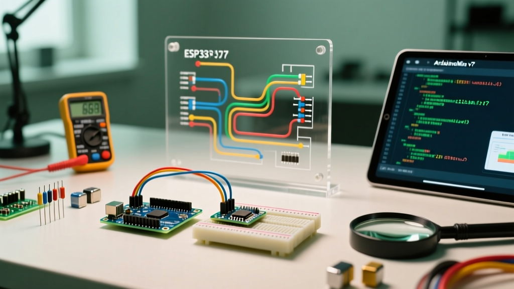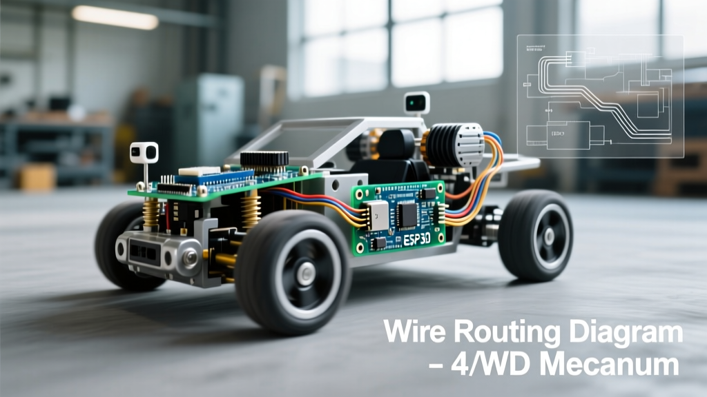

Outgrowing the Beginner Arduino Robotic Car
Building your first arduino robotic car is a rite of passage in the maker community. Kits like the Elegoo Smart Car V4.0 or the classic SunFounder 2WD chassis provide an excellent introduction to basic circuitry, motor drivers, and ultrasonic obstacle avoidance. However, as your ambitions shift from simple line-following to autonomous mapping, SLAM (Simultaneous Localization and Mapping), or payload delivery, the hardware limitations of beginner kits become glaringly obvious.
If you are experiencing severe odometry drift, I2C bus lockups, or processing bottlenecks, it is time for a migration. This guide provides a comprehensive, step-by-step upgrade path to transform a basic 2WD Arduino platform into a robust, 4WD Mecanum-wheeled autonomous rover capable of running ROS 2 (Robot Operating System) and advanced PID control loops.
Diagnosing the 2WD Bottlenecks
Before tearing down your chassis, it is critical to understand why the standard 2WD configuration fails in advanced applications:
- Odometry Drift: Standard yellow TT gearmotors lack quadrature encoders. Without wheel tick feedback, dead-reckoning navigation is impossible; a 2-degree heading error results in a massive positional drift over just three meters.
- EMI and I2C Lockups: The brushed DC motors in beginner kits generate massive electromagnetic interference (EMI). This noise couples into unshielded jumper wires, routinely freezing the MPU6050 IMU on the I2C bus and crashing the ATmega328P microcontroller.
- Payload and Traction Limits: A 2WD acrylic chassis relies on a passive caster wheel. Under heavy payloads (e.g., adding a LiDAR turret and a robotic arm), the center of gravity shifts, causing the drive wheels to slip and the caster to drag.
Phase 1: Drivetrain and Mechanical Migration
The most impactful upgrade to your arduino robotic car is replacing the TT motors and acrylic chassis with a rigid aluminum platform and encoder-equipped motors. For 2026 robotics builds, Mecanum wheels paired with JGA25 metal gearmotors represent the gold standard for indoor autonomous rovers.
Motor and Wheel Comparison Matrix
| Component | Gear Ratio | Encoder | Stall Current | Approx. Cost (2026) |
|---|---|---|---|---|
| Standard TT Motor (Yellow) | 1:48 | None | ~2.0A | $2.00 |
| Pololu JGA25 (Metal Gear) | 30:1 | Magnetic (12 CPR) | ~1.2A | $28.00 |
| DFRobot 96mm Mecanum Hub | 1:30 | Hall Effect | ~1.5A | $45.00 |
Source: Motor specifications and pricing verified via Pololu Micro Metal Gearmotor Catalog.
Migration Action: Upgrade to a 4WD aluminum chassis (such as the DFRobot or Yahboom Mecanum platforms). Ensure the motor mounts utilize M3 brass standoffs rather than plastic zip-ties to maintain wheel alignment under torque.
Phase 2: Power Architecture Overhaul
Beginner kits typically wire the logic circuits and motors to the same 2S LiPo (7.4V) battery via a cheap L298N motor driver. When the motors stall or reverse direction, they draw up to 2A per motor, causing a voltage sag that triggers a brownout reset on the Arduino Uno.
Expert Warning: The L298N Voltage Drop
The legacy L298N motor driver uses bipolar junction transistors (BJTs), which drop roughly 2V to 3V across the H-bridge. If your battery sags to 6.5V under load, your motors only see 3.5V. Solution: Migrate to a MOSFET-based driver like the TB6612FNG or DRV8835, which feature a voltage drop of less than 0.5V and support PWM frequencies up to 20kHz for silent motor operation.
Implementing a Split Power Rail
- Main Power: Use a 3S LiPo (11.1V, 2200mAh, 40C discharge) to feed the motor drivers directly.
- Logic Power: Use a high-efficiency buck converter (e.g., Pololu D24V25F5) to step the 11.1V down to a clean 5V/3.3V rail specifically for the microcontroller, LiDAR, and IMU.
- Common Ground: Ensure all grounds (Battery, Motor Driver, Buck Converter, MCU) are tied together at a single central star-ground point to prevent ground loops.
Phase 3: Compute and Sensor Migration
The Arduino Uno R3 (ATmega328P, 16MHz, 2KB SRAM) simply cannot handle the matrix math required for inverse kinematics, PID tuning, and LiDAR SLAM simultaneously. To build a modern arduino robotic car, you must migrate the compute layer.
Compute Upgrade Paths
- Path A (The ROS 2 Bridge): Upgrade to the ESP32-S3 ($12-$15). Its dual-core 240MHz processor and native WiFi allow it to run micro-ROS, acting as a hardware node that communicates via UDP to a Raspberry Pi 5 running the heavy ROS 2 Nav2 stack.
- Path B (The Standalone Powerhouse): Upgrade to the Arduino Portenta H7 ($105). Featuring a dual-core STM32H747XI (Cortex-M7 at 480MHz and Cortex-M4 at 240MHz), it can run machine learning models (TinyML) and full SLAM algorithms natively without a companion Linux computer.
For detailed pinouts and micro-ROS agent setup on ESP32, refer to the official micro-ROS documentation and the Arduino Portenta H7 hardware guide.
Sensor Upgrades: IMU and LiDAR
Ditch the MPU6050. Migrate to the BNO085 or BNO086 IMU. These sensors feature onboard sensor fusion (calculating quaternion orientation in hardware) and communicate via SPI, entirely bypassing the I2C noise issues caused by motor EMI. For mapping, integrate a Slamtec RPLIDAR A1M8 (~$100), which provides 360-degree 2D scanning at 8000 samples per second, mounting it centrally on the top acrylic plate of your new 4WD chassis.
Phase 4: Software Migration (From Delay to PID)
The most common failure mode in upgraded hardware is running legacy beginner code. If your code uses delay(), your PID loops will starve, and your robot will oscillate wildly.
Implementing Non-Blocking PID Control
You must migrate to a non-blocking architecture. Use the PID_v1 library or the more modern QuickPID library. Your main loop() should execute at a fixed interval (e.g., 50Hz / 20ms) using a hardware timer interrupt or a non-blocking millis() check.
// Pseudo-code for 50Hz PID execution
unsigned long lastTime = 0;
const int sampleTime = 20; // 20ms = 50Hz

void loop() {
  if (millis() - lastTime >= sampleTime) {
    lastTime = millis();
    readEncoders();
    computeOdometry();
    pidLeft.Compute();
    pidRight.Compute();
    applyMotorPWM();
  }
  // Handle ROS callbacks or serial comms outside the PID block
  handleMicroROS();
}
Frequently Asked Questions (FAQ)
Do I need to recalibrate my PID values after upgrading to Mecanum wheels?
Yes. Mecanum wheels introduce significant lateral slip and require an entirely different kinematic model (Holonomic drive). Standard differential drive PID tuning will fail. You must implement a 4-motor inverse kinematics matrix and tune the P, I, and D values for each wheel independently using a serial plotter to monitor step-response overshoot.
Can I keep my L298N motor driver if I upgrade to 4WD?
Technically yes, but practically no. The L298N can only handle two DC channels. To drive four motors, you would need two L298N modules, which adds massive weight, generates excessive heat, and wastes battery voltage. Migrate to a 4-channel I2C motor driver like the Adafruit Motor Shield V2 or a custom PCB utilizing dual DRV8833 chips.
How do I fix the encoder jitter I'm seeing on my new JGA25 motors?
Encoder jitter on 3.3V/5V logic microcontrollers is usually caused by voltage spikes from the motor brushes crossing the encoder threshold. Solder 0.1µF ceramic capacitors directly across the motor terminals (and from each terminal to the motor casing) to suppress high-frequency EMI. Additionally, use twisted-pair wiring for the encoder signal lines back to the Arduino.
Conclusion
Migrating your arduino robotic car from a 2WD beginner toy to a 4WD autonomous platform is a challenging but deeply rewarding engineering exercise. By systematically upgrading the drivetrain, isolating the power architecture, leveraging modern compute modules like the ESP32-S3 or Portenta H7, and implementing non-blocking PID control, you bridge the gap between hobbyist tinkering and professional robotics development. Your upgraded rover will now possess the traction, processing power, and sensor fidelity required to tackle real-world autonomous navigation challenges.