
Understanding Arduino Pressure Transducer Architectures
When integrating fluid or gas monitoring into a microcontroller project, selecting the right sensor is only half the battle. A true arduino pressure transducer differs from a simple pressure switch or a barometric air sensor (like the BMP390). Transducers output a continuous, proportional analog electrical signal based on the applied mechanical stress, making them ideal for hydraulic systems, water pump automation, and pneumatic manifolds.
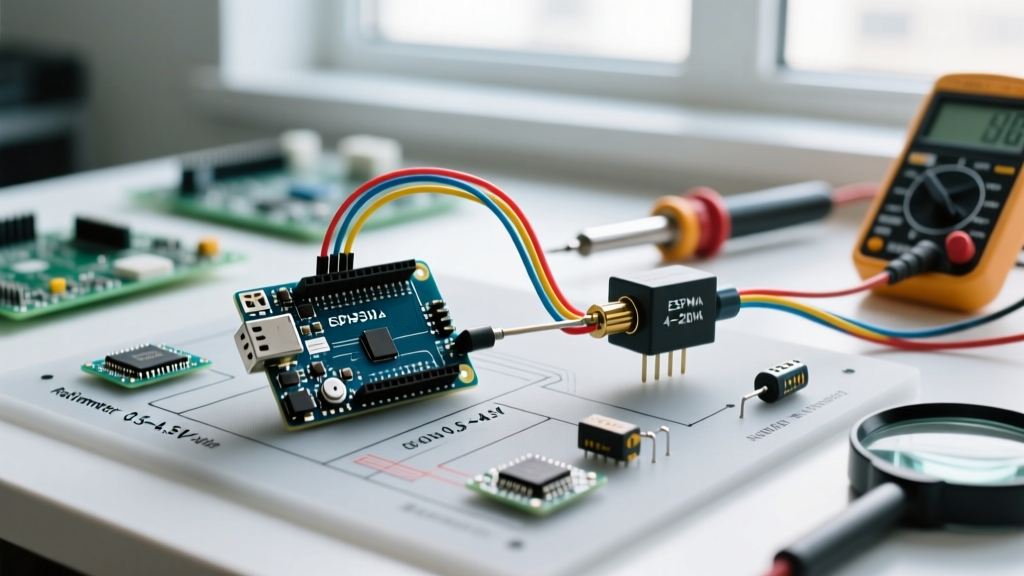
In 2026, makers and industrial prototypers generally choose between two primary analog output standards: ratiometric voltage (0.5V to 4.5V) and current loops (4-20mA). Configuring these correctly requires an understanding of analog-to-digital conversion (ADC), signal conditioning, and linear calibration mathematics.
Hardware Selection Matrix
| Transducer Type | Output Signal | Wiring Complexity | Best Use Case | Avg. Cost (2026) |
|---|---|---|---|---|
| Stainless Steel Ratiometric (e.g., 100 PSI) | 0.5V - 4.5V | Low (3-wire) | Water pressure, automotive oil, short runs (<3m) | $14 - $22 |
| Industrial Amplified | 1.0V - 5.0V | Low (3-wire) | 5V logic systems requiring max ADC resolution | $35 - $50 |
| Industrial Current Loop | 4-20mA | High (Requires shunt & external PSU) | Long cable runs, high EMI environments, factory floors | $65 - $120+ |
Configuration 1: The 0.5V-4.5V Ratiometric Transducer
The most common maker-friendly transducer is the generic 100 PSI stainless steel unit with a 1/8" NPT thread. It utilizes a Wheatstone bridge internally, amplified by an onboard IC to output a ratiometric voltage. "Ratiometric" means the output scales proportionally with the supply voltage. If your Arduino's 5V rail sags to 4.8V, the transducer's maximum output drops from 4.5V to 4.32V accordingly.
Physical Installation and Sealing
A critical failure point in fluid projects is improper thread sealing. Do not use standard PTFE (Teflon) tape on the 1/8" NPT threads if the transducer is monitoring drinking water or sensitive hydraulic valves. Shredded tape can travel downstream and block orifices. Instead, use a liquid thread sealant like Loctite 567 or a pneumatic-grade paste. Apply it only to the second and third threads to prevent sealant from squeezing into the sensor's internal diaphragm port.
Wiring to Arduino Uno R4 / Nano
- Red Wire: 5V (VCC)
- Black Wire: Ground (GND)
- Green/White Wire: Analog Input (e.g., A0)
Pro-Tip: If you are using a 3.3V microcontroller like the ESP32 or Arduino Nano 33 IoT, you must power the transducer with 3.3V (if the transducer datasheet supports a 3.3V minimum supply) or use a precision voltage divider to step the 4.5V maximum signal down to 3.3V to prevent frying the GPIO pin.
Configuration 2: The 4-20mA Industrial Current Loop
For environments with heavy electromagnetic interference (EMI) or cable runs exceeding 10 meters, voltage signals degrade due to wire resistance. The 4-20mA standard solves this by transmitting data as current, which remains constant regardless of cable length or voltage drop. As noted in Analog Devices' comprehensive guide on current loops, this standard is the backbone of industrial process control.
The Shunt Resistor Method
Microcontrollers cannot read current directly; they read voltage. To interface a 4-20mA transducer with an Arduino, you must pass the current through a precision shunt resistor to generate a proportional voltage via Ohm's Law ($V = I \times R$).
- Target Voltage: We want a 1V to 5V range to maximize the Arduino's 0-5V ADC window.
- Calculate Resistance: $R = V / I$. For 5V at 20mA (0.020A), $R = 5 / 0.020 = 250\Omega$.
- Component Selection: Use a 249\Omega 1% metal film resistor. Standard 5% carbon resistors will introduce severe calibration drift as they heat up.
Wiring the Loop
You will need an external 24V DC power supply, as Arduino's 5V rail cannot drive an industrial loop.
- 24V PSU (+) to Transducer Positive (+)
- Transducer Negative (-) to one leg of the 249\Omega shunt resistor
- Other leg of the shunt resistor to Arduino GND and 24V PSU (-)
- Arduino Analog Pin (A0) to the junction between the Transducer (-) and the shunt resistor
Warning: Never disconnect the shunt resistor while the 24V loop is powered. Without the resistor to limit voltage, the transducer's internal transmitter will attempt to drive the voltage up to its compliance limit (often 30V+), which will instantly destroy the Arduino's ATmega or RA4M1 microcontroller upon contact.
Signal Conditioning and ADC Resolution
Raw analog readings from pressure transducers are notoriously noisy due to pump vibrations and electrical switching. Before the signal reaches the ADC pin, implement a hardware low-pass RC filter. Solder a 10k\Omega resistor in series with the signal wire, and place a 0.1\µF ceramic capacitor from the Arduino-side of the resistor to Ground. This creates a single-pole filter with a cutoff frequency of roughly 160Hz, eliminating high-frequency switching noise from relays and VFDs.
Upgrading to 16-Bit Precision
The classic Arduino Uno R3 features a 10-bit ADC (1024 steps). Over a 0.5V to 4.5V span (4.0V usable), each step represents roughly 0.1 PSI on a 100 PSI sensor. While adequate for basic water pumps, it is insufficient for precision pneumatics. For high-resolution tasks in 2026, bypass the internal ADC entirely and use an external I2C ADC like the ADS1115 (16-bit). As detailed in Adafruit's ADS1115 documentation, this yields 32,768 steps, reducing the noise floor and allowing sub-0.01 PSI resolution.
Calibration Mathematics and C++ Implementation
Converting the raw ADC value into engineering units (PSI, Bar, or kPa) requires a linear mapping equation. For a standard 0.5V to 4.5V 100 PSI transducer:
- V_zero (10% VCC): 0.5V
- V_span (80% VCC): 4.0V (from 0.5V to 4.5V)
- P_max: 100 PSI
The formula is: $PSI = \frac{(V_{read} - 0.5) \times 100}{4.0}$
Production-Ready Arduino Code
The following sketch utilizes the official Arduino analogRead reference methodologies, incorporating a software moving average filter to smooth out fluid hammer spikes.
const int PRESSURE_PIN = A0;
const int NUM_READINGS = 20;
int readings[NUM_READINGS];
int readIndex = 0;
long total = 0;

// Sensor Constants (100 PSI, 0.5V - 4.5V)
const float V_SUPPLY = 5.0;
const float V_ZERO = 0.5;
const float V_SPAN = 4.0;
const float P_MAX = 100.0;
const int ADC_MAX = 1023; // Use 16383 for 14-bit Uno R4, or 32767 for ADS1115

void setup() {
  Serial.begin(115200);
  for (int i = 0; i < NUM_READINGS; i++) {
    readings[i] = 0;
  }
  // Allow analog reference to stabilize
  analogRead(PRESSURE_PIN);
  delay(100);
}

void loop() {
  total = total - readings[readIndex];
  readings[readIndex] = analogRead(PRESSURE_PIN);
  total = total + readings[readIndex];
  readIndex = (readIndex + 1) % NUM_READINGS;

  float averageADC = total / (float)NUM_READINGS;

  // Convert ADC to Voltage
  float voltage = (averageADC / ADC_MAX) * V_SUPPLY;

  // Convert Voltage to PSI
  float psi = 0;
  if (voltage > V_ZERO) {
    psi = ((voltage - V_ZERO) * P_MAX) / V_SPAN;
  }

  // Convert PSI to Bar (Optional)
  float bar = psi * 0.0689476;

  Serial.print("Voltage: "); Serial.print(voltage, 3);
  Serial.print(" V | Pressure: "); Serial.print(psi, 2);
  Serial.print(" PSI | "); Serial.print(bar, 2); Serial.println(" Bar");

  delay(50); // 20Hz update rate
}
Troubleshooting Common Edge Cases
1. The "Ghost Pressure" Drift
If your sensor reads 2 PSI when the system is fully depressurized, you are likely experiencing ground loop interference or VCC sag. Because ratiometric sensors tie their output directly to the supply rail, a 0.1V drop on the 5V USB line (common when powering servos or relays from the same rail) will shift the baseline. Solution: Power the transducer from a dedicated 5V linear regulator (like an L7805) or use an isolated DC-DC converter.
2. Negative Values at Zero Pressure
Manufacturing tolerances mean your "0.5V" zero-offset might actually be 0.48V. If the code strictly enforces `voltage > 0.5`, it will read 0. However, if the math doesn't clamp, a 0.48V reading will result in a negative PSI output. Always implement a software clamp: `if (psi < 0) psi = 0;` to prevent downstream logic errors in your pump controllers.
3. Fluid Hammer Spikes
When a solenoid valve slams shut, the kinetic energy of the fluid creates a shockwave (water hammer) that can momentarily spike pressure readings to 200% of the sensor's rated capacity, or physically rupture the diaphragm. Install a pressure snubber (a simple brass fitting with a 0.5mm pinhole restriction) between the pipe and the transducer to dampen these high-frequency hydraulic shocks.