
Why Hardware Serial Outperforms Software Alternatives in 2026
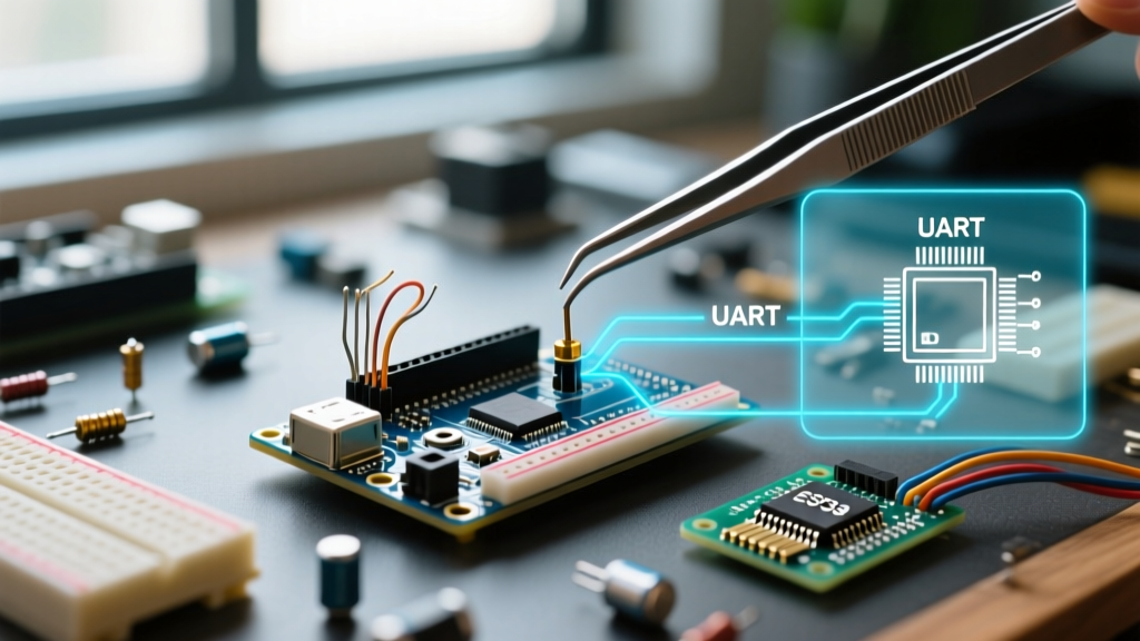
In the modern maker ecosystem, relying on SoftwareSerial for critical communication is a legacy practice that introduces severe timing bottlenecks. Arduino hardware serial leverages dedicated Universal Asynchronous Receiver-Transmitter (UART) peripherals embedded directly into the microcontroller's silicon. Unlike software-emulated UARTs—which disable global interrupts during byte transmission and reliably fail above 57,600 baud—hardware serial operates entirely in the background via Direct Memory Access (DMA) or dedicated interrupt service routines (ISRs).
Whether you are parsing NMEA sentences from a 10Hz GPS module, streaming telemetry over RS-485, or debugging an asynchronous serial link, configuring the hardware UART correctly is non-negotiable for data integrity. This guide covers advanced hardware serial configuration across modern boards, including the Renesas-based Uno R4 and the ESP32-C3/S3 architectures.
Identifying Hardware Serial Ports Across Modern Boards
Not all Arduino boards expose their hardware UARTs equally. Misidentifying a software-emulated port as a hardware port is the leading cause of dropped packets in high-speed datalogging. Below is a hardware-level breakdown of popular 2026 development boards:
| Board Model | MCU Core | HW UART Count | Default Logic Level | USB Serial Mapping |
|---|---|---|---|---|
| Uno R3 | ATmega328P | 1 (Serial) | 5V TTL | Hardware (via ATmega16U2) |
| Uno R4 WiFi ($27.50) | Renesas RA4M1 | 2 (Serial, Serial1) | 5V / 3.3V | USB-CDC (Virtual) |
| Mega 2560 ($45.00) | ATmega2560 | 4 (Serial to Serial3) | 5V TTL | Hardware (via ATmega16U2) |
| Nano ESP32 ($21.00) | ESP32-S3 | 2 (Serial, Serial1) | 3.3V TTL | USB-CDC (Virtual) |
Expert Insight: On USB-CDC boards like the Uno R4 WiFi and Nano ESP32, the primarySerialobject maps to the virtual USB port, leavingSerial1as your dedicated hardware UART for external TTL devices. Always wire external sensors toSerial1(TX1/RX1) to avoid bus contention.
Configuring Baud Rates and Clock Divisors
Setting the baud rate via Serial.begin(115200) abstracts away the complex clock divisor math, but this abstraction hides a critical vulnerability: baud rate error. The microcontroller must divide its system clock to approximate the target baud rate. If the remainder is too high, the receiver will sample bits at the wrong time, resulting in garbage characters.
The ATmega 16MHz Baud Rate Error Problem
On a classic 16MHz Uno R3, the UART Baud Rate Register (UBRR) is calculated as:
UBRR = (Fosc / (16 * BAUD)) - 1
At 115,200 baud, the ideal UBRR is 7.68. Since the register only accepts integers, it rounds to 8. This results in an actual baud rate of 111,111, yielding a -3.5% error. While tolerable for short TTL connections, a -3.5% error will cause catastrophic frame errors when paired with strict RS-485 transceivers or long cable runs.
The Fix: Use 250,000 baud or 500,000 baud. At 250,000 baud, the UBRR is exactly 3.0, resulting in a 0.0% error. Both the Arduino and the receiving peripheral (like a PC with a custom USB-UART bridge) must be configured to match this non-standard but mathematically perfect baud rate.
Double-Speed Mode (U2X)
For AVR boards, the Arduino core automatically enables the U2Xn (Double Speed) bit when necessary to reduce baud rate error. However, if you are writing bare-metal register configurations or using custom bootloaders, ensure the U2X bit is set, which changes the divisor from 16 to 8, drastically improving resolution at higher speeds.
Advanced Buffer Management & Interrupt Tuning
By default, the Arduino core allocates a 64-byte ring buffer for hardware serial RX. If your sketch experiences a blocking delay (e.g., writing to an SD card or updating a TFT display via SPI) and more than 64 bytes arrive at the UART, the buffer overflows. The UART peripheral will flag an overrun error, and all subsequent incoming bytes will be silently dropped until the buffer is read.
Increasing the RX Buffer Size in Arduino IDE 2.x
Modifying core library files (like HardwareSerial.h) is a bad practice that breaks upon core updates. Instead, override the buffer size using build flags. For ESP32 and RP2040 cores, you can define the buffer size in your platformio.ini or via the IDE's custom build settings.
For standard AVR boards, create a platform.local.txt file in the core's hardware directory and append the following compiler flag to inject a larger buffer size before compilation:
compiler.c.extra_flags=-DSERIAL_RX_BUFFER_SIZE=256
compiler.cpp.extra_flags=-DSERIAL_RX_BUFFER_SIZE=256
This expands the ring buffer to 256 bytes, providing enough headroom to safely parse 200-byte NMEA GPS sentences even if the MCU is busy performing a 50ms I2C transaction with a BME280 sensor.
Hardware Flow Control (RTS/CTS) Configuration
When streaming megabytes of telemetry data from an Arduino Nano ESP32 to a cellular modem, software buffers are insufficient. You must implement hardware flow control using RTS (Request to Send) and CTS (Clear to Send) lines. According to the official Espressif UART documentation, the ESP32's UART peripheral can autonomously pause transmission when the CTS line is de-asserted by the receiver.
- Wiring: Connect ESP32 GPIO 18 (CTS) to the modem's RTS pin, and ESP32 GPIO 19 (RTS) to the modem's CTS pin.
- Configuration: Use the ESP32-specific
Serialextensions in yoursetup()function.
Serial1.begin(921600);
// Set pins: RX, TX, CTS, RTS
Serial1.setPins(16, 17, 18, 19);
Serial1.setHwFlowCtrlMode(UART_HW_FLOWCTRL_CTS_RTS, 64);
This configuration tells the UART peripheral to automatically halt outgoing data if the receiver's buffer is within 64 bytes of capacity, eliminating packet loss without requiring a single line of polling code in your main loop.
Troubleshooting Common Hardware Serial Failures
Even with perfect code, physical layer issues will corrupt hardware serial data. Use this diagnostic matrix to isolate failures:
1. Garbage Characters and Framing Errors
- Cause: Baud rate mismatch or incorrect stop-bit/parity configuration. The Arduino Serial Reference defaults to 8N1 (8 data bits, No parity, 1 stop bit).
- Fix: If communicating with industrial PLCs or legacy RS-232 equipment, you may need 7E1 (7 data, Even parity, 1 stop). Use
Serial.begin(9600, SERIAL_7E1)to configure the hardware UART registers for parity generation.
2. RS-485 Half-Duplex DE/RE Pin Contention
When using a MAX485 transceiver for industrial noise immunity, you must toggle the Driver Enable (DE) pin HIGH to transmit and LOW to receive. A common mistake is toggling the pin immediately after calling Serial.print(). Because hardware serial is non-blocking, Serial.print() merely loads the buffer and returns instantly. If you pull DE LOW immediately, the transceiver cuts off before the first bit is sent.
The Fix: Always call Serial.flush() before pulling the DE pin LOW. Serial.flush() blocks the MCU until the hardware shift register is completely empty and the final stop bit has cleared the TX pin.
3. Logic Level Mismatch (3.3V vs 5V)
Connecting a 5V Mega 2560 TX pin directly to a 3.3V ESP32 or SIM7000 LTE modem RX pin will slowly degrade the receiving silicon, eventually causing permanent port failure due to latch-up.
- Bad Fix: Using a simple resistor voltage divider. This increases impedance and ruins signal integrity above 38,400 baud, causing rounded signal edges and bit errors.
- Expert Fix: Use a dedicated bi-directional logic level shifter IC like the SN74LVC2T45 or TXB0102. These cost less than $0.50 in single quantities, maintain sharp nanosecond rise times, and guarantee safe 5V-to-3.3V translation at baud rates exceeding 2 Mbps.
Frequently Asked Questions
Can I use Serial and Serial1 simultaneously?
Yes. On boards with multiple hardware UARTs (like the Mega 2560 or Uno R4), each Serial object operates on independent hardware peripherals with dedicated ISRs and ring buffers. You can log debug data to USB via Serial while simultaneously reading a GPS module on Serial1 without cross-interference.
Does hardware serial consume PWM timers?
No. Unlike SoftwareSerial or Servo libraries that hijack Timer1 or Timer2, hardware UART relies on its own dedicated baud-rate generator circuitry. Enabling hardware serial will never disrupt your analogWrite() PWM frequencies or interrupt-driven motor control loops.
How do I detect if the serial cable was disconnected?
Standard TTL UART does not have a physical 'link state' pin. If you require connection monitoring, you must either implement a software-level heartbeat (ping/pong) over the data lines, or utilize an RS-232 transceiver that exposes the DCD (Data Carrier Detect) or DSR (Data Set Ready) pins to a GPIO interrupt.