
The Fundamental Concept: Why Arduino Needs a CAN Shield
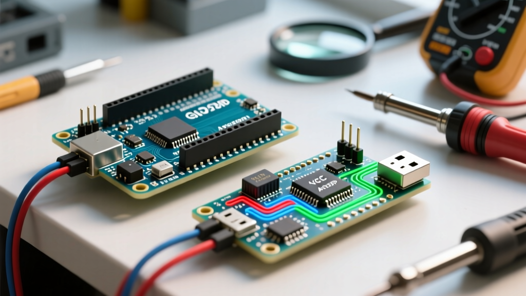
The Controller Area Network (CAN) protocol is the backbone of modern automotive and industrial communication. Unlike simple UART or I2C protocols, CAN is a robust, multi-master, message-based differential bus designed to operate in high-noise environments. However, the standard ATmega328P microcontroller found on the Arduino Uno lacks a native CAN peripheral. While newer boards like the ESP32 or Teensy 4.1 feature native CAN controllers, they still require external transceivers to interface with the physical bus. For classic Arduino boards, an Arduino CAN bus shield is strictly required to bridge the gap between the microcontroller's SPI bus and the physical CAN network.
Understanding the architecture of these shields is critical for makers attempting to read OBD-II engine data, interface with industrial PLCs, or build custom drone telemetry networks. A CAN shield is not just a simple level shifter; it is a complex protocol engine that handles frame arbitration, CRC validation, and fault confinement in hardware, freeing your Arduino's CPU to focus on application logic.
Inside the Shield: Controller vs. Transceiver Architecture
Every functional Arduino CAN bus shield relies on a two-chip architecture. Confusing the roles of these two chips is the most common beginner mistake when troubleshooting bus errors.
1. The CAN Controller (Protocol Engine)
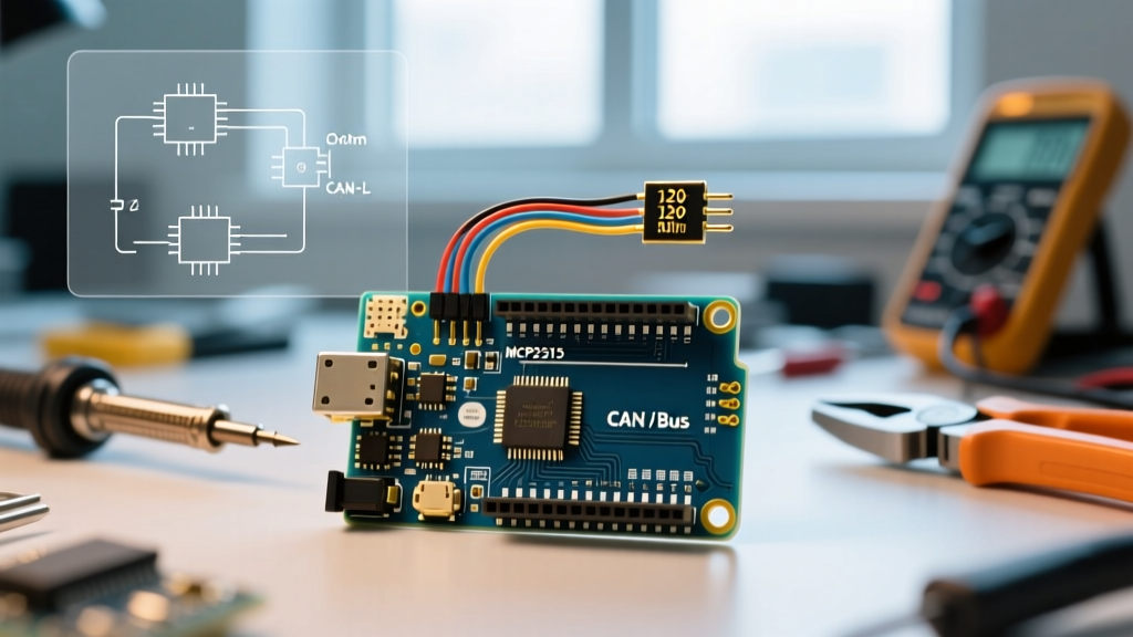
The controller handles the data link layer. The undisputed industry standard for Arduino shields is the Microchip MCP2515. It connects to the Arduino via the SPI bus (using pins 11, 12, 13, and a Chip Select pin, usually 9 or 10). The MCP2515 supports Classic CAN up to 1 Mbps. For advanced applications requiring CAN FD (Flexible Data-rate) to achieve speeds up to 8 Mbps, newer shields utilize the MCP2518FD. The controller manages message buffers, acceptance masks, and filters, meaning your Arduino only receives interrupts for messages that match your predefined criteria.
2. The CAN Transceiver (Physical Layer)
The controller speaks SPI; the transceiver translates those logic-level signals into the differential voltages required by the CAN bus. The transceiver connects to the controller via CAN-TX and CAN-RX pins. Common transceivers found on shields include:
- TJA1050 / MCP2551: Older, robust 5V transceivers. They are standard on Seeed Studio and generic clone shields. They are strictly 5V devices and will damage 3.3V microcontrollers if wired directly.
- SN65HVD230 / TJA1042: 3.3V transceivers. Essential if you are adapting a shield for use with an ESP32, Arduino Due, or Teensy.
The SPI Bottleneck: Timing and Interrupts
Because classic Arduino shields rely on SPI to communicate with the MCP2515, latency is introduced. At a standard 16 MHz clock, the Arduino Uno's SPI bus can theoretically transfer data at 8 Mbps, but the overhead of SPI register reads/writes means fetching a CAN frame takes approximately 15 to 20 microseconds. If you are operating on a busy 1 Mbps CAN bus, the MCP2515's internal buffers (which hold a maximum of three receive frames) can overflow if your Arduino sketch spends too much time inside blocking functions like delay() or Serial.print(). Always use hardware interrupts (INT pin) to trigger frame reads rather than polling the controller.
2026 Hardware Comparison: Top Arduino CAN Bus Shields
The market for CAN shields has matured. Below is a comparison of the most reliable hardware options available for prototyping and production.
| Shield / Module | Controller | Transceiver | Logic Level | Approx. Price (2026) | Best Use Case |
|---|---|---|---|---|---|
| Seeed Studio CAN-BUS V2.0 | MCP2515 | MCP2551 | 5V | $22.00 | Standard Arduino Uno automotive OBD-II projects |
| SparkFun CAN-BUS Shield | MCP2515 | MCP2551 | 5V | $34.95 | Education, robust headers, integrated GPS/uSD |
| Waveshare CAN FD Shield | MCP2518FD | SN65HVD230 | 3.3V / 5V | $28.50 | CAN FD networks, high-speed data logging |
| Generic eBay MCP2515 Module | MCP2515 | TJA1050 | 5V | $2.50 | Budget prototyping, breadboard wiring |
The Physical Layer: Wiring and the 120-Ohm Rule
CAN uses differential signaling across two wires: CAN-High (CANH) and CAN-Low (CANL). The receiver calculates the difference in voltage between these two lines to determine if a bit is a dominant '0' or a recessive '1'. This differential approach is what grants CAN its legendary immunity to electromagnetic interference (EMI).
The Termination Mandate: A CAN bus must be terminated at both physical ends of the network with a 120-ohm resistor placed between CANH and CANL. Without these termination resistors, signals reflect off the open ends of the wire, causing destructive interference and resulting in immediate bus errors. Most high-quality Arduino CAN bus shields include a 120-ohm resistor with a jumper or slide switch to enable or disable it. If your Arduino is the only node on the bus alongside an ECU, ensure both the shield and the ECU have their 120-ohm terminators active (yielding a parallel resistance of ~60 ohms).
Multimeter Debugging: The Voltage Test
Before uploading a single line of code, verify your physical layer with a digital multimeter. Set it to DC voltage and measure between the bus wires and ground.
- Recessive State (Idle): CANH should read ~2.5V, and CANL should read ~2.5V. The differential voltage is 0V.
- Dominant State (Active): CANH should rise to ~3.5V, and CANL should drop to ~1.5V. The differential voltage is 2.0V.
- Total Resistance Check: With all power disconnected, measure resistance between CANH and CANL. A properly terminated bus will read 60 ohms. If it reads 120 ohms, you are missing one terminator. If it reads near 0 ohms, you have a short circuit.
Real-World Failure Modes and Edge Cases
When working with an Arduino CAN bus shield, hardware integration issues often masquerade as software bugs. Watch out for these specific failure modes:
- Ground Loops and Common Mode Voltage: The transceivers can only tolerate a limited voltage difference between the grounds of different nodes (typically up to ±12V for TJA1050). If your Arduino is powered by a laptop via USB, and the target vehicle ECU is grounded to the chassis, differences in ground potential can fry the transceiver. Always use isolated DC-DC converters or opto-isolated CAN transceivers for automotive bench testing.
- OBD-II Pinout Confusion: When connecting to a car's SAE J1962 diagnostic port, CAN-H is on Pin 6 and CAN-L is on Pin 14. However, older vehicles might use J1850 PWM/VPW or ISO 9141-2 (K-Line) on different pins. Ensure the vehicle actually outputs CAN on the OBD-II port before assuming your shield is broken.
- Missing Crystal Oscillator Configuration: Generic MCP2515 modules often ship with an 8 MHz crystal, while the Seeed Studio shield uses a 16 MHz crystal. If your software library is initialized with the wrong clock speed, the baud rate calculation will be completely wrong, and the bus will reject your frames as bit-errors.
Software Stack: Moving Beyond Basic Libraries
For classic MCP2515 shields, the MCP_CAN library by Cory Fowler remains the gold standard in the Arduino ecosystem. It provides reliable initialization and frame parsing. However, for advanced applications like reading engine telemetry, you must understand OBD-II PIDs (Parameter IDs).
Reading data like RPM or coolant temperature requires sending a multi-byte request frame (usually ID 0x7DF) and parsing a multi-frame response. Because OBD-II responses often exceed the 8-byte limit of Classic CAN, the ECU uses ISO 15765-2 (CAN Transport Protocol) to split the data into First Frames and Consecutive Frames. Your Arduino sketch must be programmed to send Flow Control (FC) frames back to the ECU to prompt it to send the remaining data chunks. Failing to implement Flow Control is the primary reason beginners only receive the first 4 bytes of an OBD-II response.
For those utilizing modern hardware, exploring Seeed Studio's official documentation provides excellent baseline examples for SPI pin remapping, which is vital if you are stacking the CAN shield on top of an Ethernet or motor control shield that also requires the hardware SPI bus.
Summary Checklist for Successful Integration
- Verify 120-ohm termination at both ends of the bus (measure for 60 ohms).
- Confirm transceiver logic voltage matches your microcontroller (5V vs 3.3V).
- Connect the INT pin from the shield to a hardware interrupt pin on the Arduino (e.g., Pin 2 on Uno).
- Ensure the SPI Chip Select (CS) pin does not conflict with other stacked shields.
- Match the library's crystal oscillator initialization (8MHz vs 16MHz) to the physical hardware.
Mastering the Arduino CAN bus shield unlocks the ability to interface with millions of vehicles, industrial robots, and marine networks. By respecting the physical layer requirements and understanding the SPI-to-CAN translation architecture, you can build robust, noise-immune systems that perform reliably in the harshest environments.