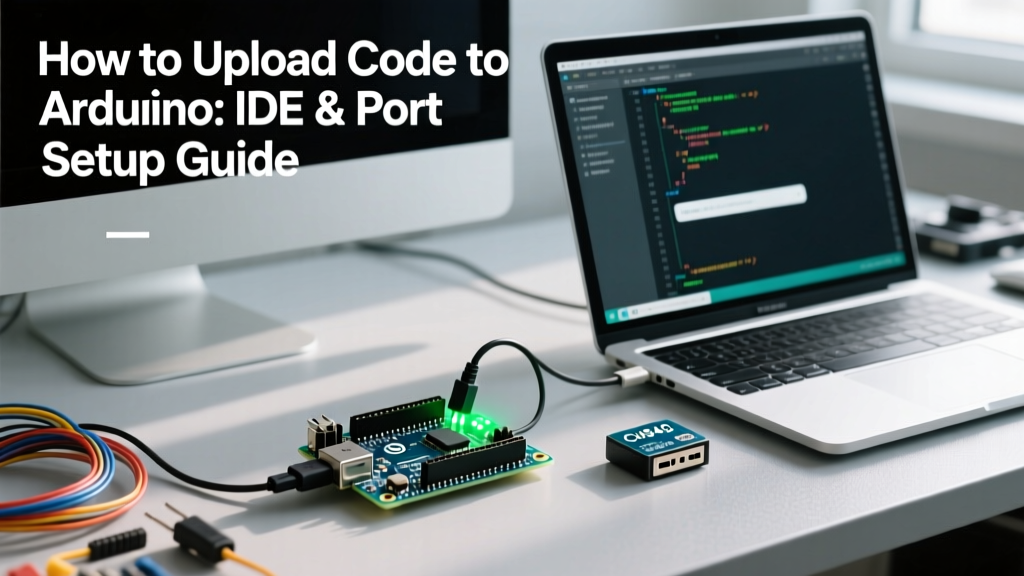

The Serial Handshake: Understanding the Upload Process
When makers ask how to upload code to Arduino, they are often looking for a simple software tutorial. However, from an electrical engineering perspective, uploading firmware is fundamentally a serial communication event. It requires a flawless physical connection, correct driver translation, and a precise UART handshake between your host machine and the microcontroller unit (MCU). Whether you are flashing an ATmega328P on a classic Uno or an RA4M1 on the newer Arduino Uno R4 Minima, the underlying principle remains identical: your PC must assert a reset signal, synchronize baud rates, and stream compiled hex data over a serial bridge.
In this communication setup guide, we bypass the basic 'click the arrow' advice and dive deep into the protocol layer. We will cover USB-to-serial bridge architectures, driver configurations for clone boards, and advanced troubleshooting for the most common avrdude communication failures encountered in the Arduino IDE 2.3.x environment.
Step-by-Step: Establishing the Physical and Driver Layer
Before the Arduino IDE can compile and transmit your C++ sketch, the operating system must recognize the development board as a valid serial communication port. Here is the precise sequence to establish that link.
1. Verify the Physical Data Layer
Over 40% of initial upload failures in educational labs stem from using charge-only USB cables. A charge-only cable lacks the D+ and D- data lines required for UART communication.
- For Arduino Uno R3 / Nano Clones: Use a verified USB-A to USB-B or Micro-USB data cable. Ensure the cable is under 2 meters to prevent voltage drop and signal degradation on the USB 2.0 bus.
- For Arduino Uno R4 / Nano ESP32: These modern boards utilize USB-C. Ensure your cable supports data transfer (USB 2.0 minimum) and that you are plugged directly into a motherboard I/O port, not an unpowered front-panel hub, to guarantee stable 5V/500mA power delivery during the flash cycle.
2. Install the Correct USB-to-Serial Drivers
Genuine Arduino boards typically use the ATmega16U2 or native USB controllers, which are natively recognized by Windows 11, macOS, and Linux. However, cost-effective third-party boards rely on third-party bridge ICs that require manual driver installation.
Pro Tip: If you plug in a clone Arduino Nano and Windows Device Manager shows 'Unknown Device' under 'Other Devices', you almost certainly have a board with a WCH CH340 chip. You must download and install the official CH340 VCP (Virtual COM Port) driver before the IDE will detect it.
For boards utilizing the Silicon Labs CP2102N chip, you can source the latest Virtual COM Port drivers directly from the Silicon Labs CP210x developer portal. Always match the driver architecture (ARM64 vs x64) to your host OS.
3. Configure the Arduino IDE Communication Parameters
Open Arduino IDE 2.3.x and navigate to Tools > Board. Select your exact hardware model. Next, go to Tools > Port. You should see a COM port (Windows) or a /dev/cu.usbmodem... or /dev/tty.usbserial... path (macOS/Linux). Select the port that explicitly lists your board's bridge chip or MCU name. If multiple ports appear, unplug the board, note which port disappears, and reconnect to identify the correct interface.
USB-to-Serial Bridge ICs: What is Actually on Your Board?
To troubleshoot communication errors effectively, you must know which bridge IC is translating your PC's USB signals into the 5V or 3.3V TTL UART signals the MCU understands. Below is a comparison of the most common bridge chips you will encounter when figuring out how to upload code to Arduino hardware.
| Bridge IC | Typical Board Usage | Driver Requirement | Max Baud Rate | Auto-Reset Support |
|---|---|---|---|---|
| ATmega16U2 | Genuine Uno R3, Mega 2560 | Native (CDC-ACM) | 2 Mbps | Yes (via DTR) |
| CH340G / CH340C | Clone Nanos, Uno R3 Clones | WCH CH340 VCP | 2 Mbps | Yes (via DTR) |
| CP2102N | NodeMCU, ESP32 DevKit V1 | Silicon Labs CP210x | 3 Mbps | Yes (via DTR/RTS) |
| FT232RL | Arduino Nano (Older Genuine), FTDI Cables | FTDI VCP | 3 Mbps | Yes (via DTR) |
| Native USB | Uno R4, Leonardo, Nano 33 IoT | Native (CDC-ACM) | USB 2.0 Speeds | Yes (Software 1200bps reset) |
Troubleshooting Communication & Upload Failures
When the serial handshake fails, the Arduino IDE relies on the avrdude (for AVR) or bossac/esptool (for ARM/ESP) command-line utilities to report the error. Understanding these specific error codes is critical for resolving upload blocks.
The 'avrdude: stk500_recv(): programmer is not responding' Error
This is the most infamous communication error in the Arduino ecosystem. It means the PC sent a synchronization request (STK500 protocol), but the MCU bootloader did not reply. According to the official Arduino troubleshooting documentation, this usually points to one of three hardware-level communication failures:
- Missing Auto-Reset Circuit: On AVR boards, the DTR (Data Terminal Ready) line from the USB bridge is routed through a 100nF (0.1µF) capacitor to the MCU's RESET pin. This momentarily pulls the reset pin low, triggering the bootloader. On ultra-cheap clones, this capacitor is sometimes omitted or soldered poorly. Fix: Press and hold the physical RESET button on the board, click 'Upload' in the IDE, and release the button exactly when the IDE console says 'Uploading...'.
- Wrong Board Selected: If you select 'Arduino Uno' but are actually using an 'Arduino Nano' with the 'Old Bootloader', the IDE attempts to communicate at 115200 baud, while the older Nano bootloader expects 57600 baud. Fix: Change Tools > Processor to 'ATmega328P (Old Bootloader)'.
- Pin 0 and 1 Interference: Digital pins 0 (RX) and 1 (TX) are hardwired to the serial bridge. If you have external sensors, motors, or shields connected to these pins, they will corrupt the UART data lines during the upload handshake. Fix: Disconnect all wiring from pins 0 and 1 before uploading.
Serial Port Collision: 'Port Already in Use'
If your IDE throws a Serial port 'COMX' already in use error, another process has established an exclusive lock on the UART stream. This frequently happens if:
- You left the Arduino IDE Serial Monitor or Serial Plotter open while trying to compile and upload a new sketch. The monitor holds the COM port open at a specific baud rate (e.g., 9600), blocking the bootloader sync.
- Background software like Cura (3D printing slicers), OctoPrint, or generic serial terminal apps (PuTTY, TeraTerm) are actively polling COM ports for connected devices.
- Fix: Close the Serial Monitor, shut down background slicing software, and physically disconnect/reconnect the USB cable to force the OS to release the file handle on the port.
The Native USB '1200 BPS Reset' Quirk
Boards with native USB capabilities (like the Arduino Leonardo, Micro, or the modern Uno R4 Minima) do not have a separate USB-to-Serial bridge chip. The MCU handles USB directly. To trigger the bootloader for uploading, the IDE uses a clever software trick: it opens the serial port at exactly 1200 baud and then immediately closes it. The MCU's firmware detects this specific, unusually slow baud rate as a signal to reset into bootloader mode.
If your native USB board becomes 'bricked' due to a bad sketch that crashes the USB stack before the 1200 bps signal can be processed, the port will disappear from the IDE. To recover it, double-tap the physical RESET button on the board rapidly. This forces the hardware bootloader to start and exposes the port just long enough for you to click 'Upload'.
Beyond USB: Network and ISP Uploads
While USB serial is the standard, understanding alternative communication protocols for uploading code is essential for advanced deployments where physical access is restricted.
Over-The-Air (OTA) via WiFi
If you are using a network-capable board like the Arduino Nano ESP32 or a generic ESP8266, you can upload code wirelessly. By including the ArduinoOTA library in your initial base sketch and connecting the board to your local 2.4GHz WiFi network, the MCU opens a TCP listening port (usually 3232 or 8266). Once configured, the board appears under Tools > Network Ports in the IDE. This eliminates USB wear-and-tear and is the industry standard for deploying firmware updates to enclosed IoT sensors.
ICSP (In-Circuit Serial Programming)
When the UART bootloader is corrupted, or when you need to flash raw C code without the Arduino bootloader overhead (saving ~2KB of flash memory), you bypass serial communication entirely. Using an ISP programmer (like the USBasp or another Arduino configured as 'Arduino as ISP'), you connect to the 6-pin ICSP header. This utilizes the SPI (Serial Peripheral Interface) protocol—specifically MOSI, MISO, SCK, and RESET lines—to write directly to the MCU's flash memory at the hardware level. For a deeper dive into the electrical signaling of SPI versus UART, refer to this comprehensive serial communication guide by SparkFun.
Summary
Mastering how to upload code to Arduino requires looking past the IDE's graphical interface and understanding the serial communication pipeline. By verifying your physical data cables, installing the correct VCP drivers for your specific bridge IC, and understanding the hardware-level reset mechanisms (DTR vs. 1200bps), you can systematically diagnose and resolve any upload failure. Treat every upload as a delicate UART negotiation, and your development workflow will become significantly more robust.