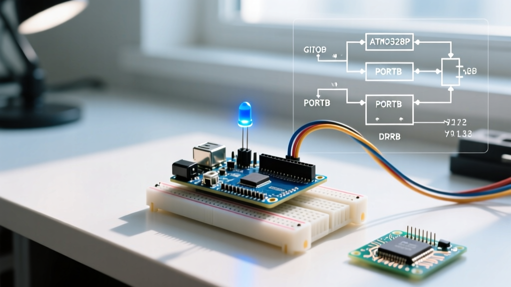

The fundamental arduino led blink code requires configuring a microcontroller pin as an OUTPUT and toggling its state between HIGH and LOW using a time delay. For beginners, hobbyists, and embedded systems students, this routine serves as the foundational validation test for hardware and software integration. The simplest implementation relies on the blocking `delay()` function, though modern production firmware demands non-blocking timing protocols to maintain system responsiveness.
- The basic blink script uses `digitalWrite()` and `delay()` but halts all other processing.
- Non-blocking protocols utilizing `millis()` allow concurrent sensor reading and LED control.
- Hardware selection dictates current-limiting resistor values; a 220-ohm resistor is standard for 5V logic.
The Standard Arduino LED Blink Code
The default script initializes a specific digital pin, typically pin 13 on legacy boards or the designated LED_BUILTIN constant on modern architectures. During the setup phase, the pin mode is declared. The main loop then applies 5V to the pin, waits, removes the voltage, and waits again.
Circuit Setup and Hardware Requirements
When wiring an external Light Emitting Diode to an Arduino Uno Rev3, you must manage electrical current to prevent component failure. The microcontroller outputs 5V logic. A standard 5mm Light Emitting Diode requires a 220-ohm current-limiting resistor to restrict the electrical flow to a safe 20 mA threshold. Exceeding this limit degrades the semiconductor junction.
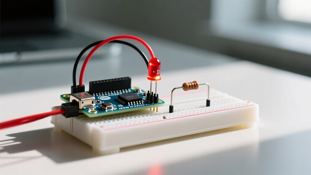
According to the official Arduino Uno Rev3 documentation, the absolute maximum current draw for any single I/O pin is 40 mA, but 20 mA is the recommended operational ceiling for long-term reliability.
The Delay Function Explained
The `delay()` command accepts an integer representing time in milliseconds. A value of 1000 milliseconds equals one second. While effective for basic validation, this function is inherently blocking. The central processing unit cannot execute sensor readings, motor controls, or wireless communication while the delay timer is active.
Non-Blocking Timing Protocols
Search queries frequently seek an 'arduino blink without delay' solution to overcome the limitations of the standard script. Non-blocking timing allows the microcontroller to track time while simultaneously executing other instructions in the main loop.
Using the Millis Function
Millis Function: A built-in Arduino Integrated Development Environment command that returns the number of milliseconds passed since the microcontroller board began running the current program. It enables non-blocking time tracking without halting the central processing unit, facilitating multitasking in embedded systems.
By storing the previous timestamp and comparing it against the current `millis()` value, the firmware determines if the designated interval has elapsed. This state-machine approach is detailed in the Arduino millis() language reference.
State Machine Implementation
Implementing a state machine requires tracking the current status of the Light Emitting Diode. If the interval passes and the light is ON, the code turns it OFF and records the new timestamp. This logic prevents the system from freezing during the wait period.
Advanced Timing: Multiple LEDs and PWM
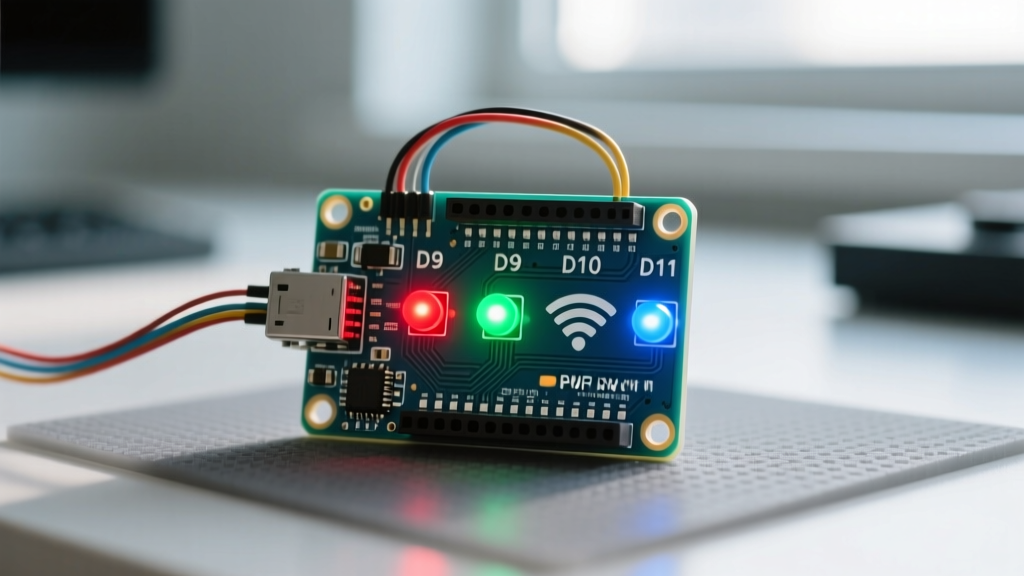
Developers scaling their projects often search for 'arduino multiple led blink code' or 'arduino pwm led fade code' to create complex visual feedback systems. Managing multiple independent timing intervals requires an array of timestamp variables and state trackers.
Pulse Width Modulation for Fading
Pulse Width Modulation: A technique used to get analog results with digital means. It creates a square wave signal where the time proportion of the HIGH state versus the LOW state is varied to simulate a specific voltage level between 0 and 5 volts for dimming applications.
The Arduino Uno R4 WiFi features a 48 MHz Arm Cortex-M4 processor, allowing highly precise Pulse Width Modulation frequencies. As noted in the Arduino Uno R4 WiFi hardware specifications, this architecture supports advanced timing arrays and hardware-driven waveform generation without software overhead.
Comparison Matrix: Timing Methods
| Feature | Blocking (delay) | Non-Blocking (millis) | Hardware Timer / RTOS |
|---|---|---|---|
| CPU Availability | Halted | Free | Free / Managed |
| Code Complexity | Low | Medium | High |
| Memory Overhead | Minimal | Low (Variables) | High (Kernel/Stacks) |
| Use Case | Prototyping | Standard Production | Complex Industrial IoT |
Frequently Asked Questions
How do I change the blink speed?
Modify the integer value passed to the timing function. In a blocking script, change the `delay()` parameter. In a non-blocking script, update the `interval` variable representing the target milliseconds.
Can I use the built-in LED for external circuits?
The onboard Light Emitting Diode is tied to a specific digital pin, usually pin 13. You can wire external components to this pin, but you must account for the existing onboard resistor and buffer operational amplifier present on most modern development boards.
Why is my LED flickering instead of blinking?
Flickering occurs when the delay interval is set below the human eye persistence of vision threshold, typically under 10 milliseconds. Ensure your timing variables are correctly scoped and not resetting unintentionally within the main loop.
Conclusion
Mastering the arduino led blink code requires transitioning from simple blocking delays to robust, non-blocking timing protocols. Understanding how to manipulate time via the `millis()` function and hardware timers ensures your microcontroller remains responsive to external inputs. Your next step is to explore hardware interrupts, which allow external signals to instantly trigger timing events without continuous software polling.