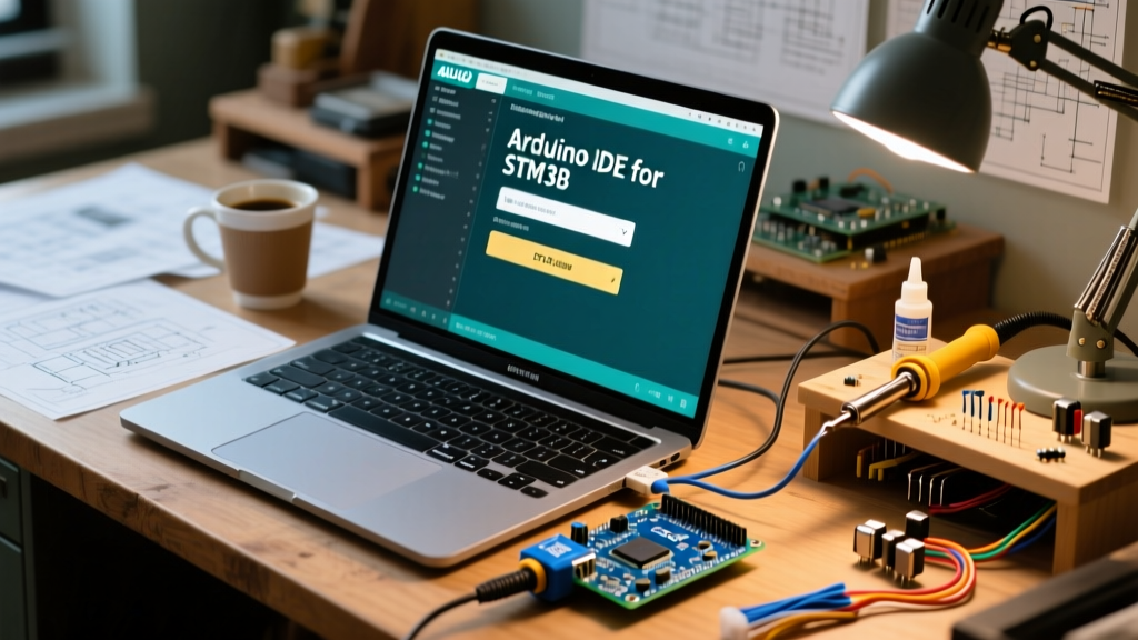

Why Transition to the Arduino IDE for STM32?
If you have outgrown the 8-bit ATmega328P found on the classic Arduino Uno, stepping into the 32-bit ARM Cortex-M ecosystem is the logical next step. Using the Arduino IDE for STM32 microcontrollers allows you to leverage the familiar C++ wiring framework while accessing vastly superior processing power, larger memory footprints, and advanced peripherals like hardware floating-point units (FPU) and native USB.
However, the STM32 ecosystem is notoriously fragmented. Unlike the plug-and-play nature of official Arduino boards, configuring the Arduino IDE for STM32 requires specific board manager packages, external programmers, and an understanding of hardware quirks. This guide cuts through the noise, providing a definitive, up-to-date pathway to get your first STM32 board blinking and compiling in 2026.
Hardware Selection: Blue Pill vs. Black Pill vs. Nucleo
Before writing code, you need the right hardware. The market is flooded with STM32 development boards, but they are not created equal. Below is a comparison of the three most common entry-point boards.
| Board Name | MCU Part Number | Flash / SRAM | Clock Speed | Typical Price (2026) | Best For |
|---|---|---|---|---|---|
| Blue Pill | STM32F103C8T6 | 64KB / 20KB | 72 MHz | $3.50 - $5.00 | Basic GPIO, learning SWD |
| Black Pill | STM32F401CCU6 | 256KB / 64KB | 84 MHz | $6.00 - $9.00 | DSP, FPU math, USB projects |
| Nucleo-64 | STM32F411RE | 512KB / 128KB | 100 MHz | $18.00 - $22.00 | Professional prototyping, reliable debugging |
Expert Tip: While the Blue Pill is the cheapest, the market is saturated with clone chips (like CKS32 or GD32) masquerading as genuine STMicroelectronics silicon. For a frustration-free first experience, the Black Pill (STM32F401) or an official ST Nucleo board is highly recommended.
Step-by-Step: Installing the STM32 Core
To use the Arduino IDE for STM32, you must install the official core maintained by STMicroelectronics and the open-source community. Do not rely on outdated, third-party 'Roger Clark' cores from 2018; the official STM32duino Core is the modern standard.
- Add the Board Manager URL: Open the Arduino IDE, navigate to File > Preferences, and paste the following URL into the 'Additional Boards Manager URLs' field:
https://github.com/stm32duino/BoardManagerFiles/raw/main/package_stmicroelectronics_index.json - Install the Core: Open the Boards Manager (Tools > Board > Boards Manager), search for STM32 MCU based boards, and click Install. (Note: This package is large, roughly 150MB, as it includes the ARM GCC toolchain).
- Install STM32CubeProgrammer: Modern versions of the STM32duino core require ST's official flashing utility to communicate with ST-Link programmers. Download and install STM32CubeProgrammer from the ST website and ensure its CLI binaries are added to your system PATH.
Configuring the Upload Method: ST-Link V2 vs. Serial
Unlike standard Arduinos that feature a built-in USB-to-Serial bootloader, most raw STM32 boards require an external programmer. The ST-Link V2 is the industry standard for Serial Wire Debug (SWD).
Wiring the ST-Link V2 to a Blue Pill
You only need four wires to establish a full debug and upload connection. Never connect the 5V pin of the ST-Link to the 3.3V pin of the STM32, or you will instantly destroy the microcontroller.
- GND (ST-Link) to GND (STM32)
- 3.3V (ST-Link) to 3.3V (STM32)
- SWDIO (ST-Link) to DIO (STM32)
- SWCLK (ST-Link) to CLK (STM32)
IDE Menu Configuration
Once wired, configure your Arduino IDE environment under the Tools menu:
- Board: Select your specific chip (e.g., 'Generic STM32F1 series').
- Board part number: Match your exact silicon (e.g., 'BluePill F103C8').
- Upload method: Select STM32CubeProgrammer (SWD).
- U(S)ART support: Enable 'First (default)' if you plan to use Serial.print() for debugging via the PA9/PA10 pins.
Your First Sketch: The 'Active LOW' Trap
When writing your first Blink sketch, beginners often copy standard Arduino code and wonder why the LED behaves inversely or not at all. On the vast majority of Blue Pill and Black Pill boards, the onboard LED is connected to pin PC13 and is wired Active LOW. This means writing a LOW signal turns the LED ON, and HIGH turns it OFF.
void setup() {
  // Initialize PC13 as an output
  pinMode(PC13, OUTPUT);
}

void loop() {
  digitalWrite(PC13, LOW);  // Turn the LED ON (Active LOW)
  delay(500);
  digitalWrite(PC13, HIGH); // Turn the LED OFF
  delay(500);
}
For a deeper understanding of how Arduino Cores map hardware abstractions to different architectures, reviewing the official Arduino documentation is highly recommended.
Advanced Troubleshooting & Edge Cases
Working with the Arduino IDE for STM32 introduces hardware-level variables that do not exist in the 8-bit AVR world. Here are the most common failure modes and their precise solutions.
1. The 'Fake Chip' Flash Verification Error
Symptom: The code compiles, uploads, but throws a 'Flash verification failed' or 'No target found' error at the very end.
Root Cause: You purchased a Blue Pill with a clone chip (e.g., CKS32F103C8T6 or GD32F103C8T6). The ST-Link reads the chip ID, realizes it does not match the genuine ST signature, and aborts the verification step.
Solution: In the Arduino IDE Tools menu, change the 'Board part number' to match the clone if available, or simply uncheck Verify code after upload in the IDE preferences. The code will still run perfectly on the clone silicon.
2. Linux 'LIBUSB_ERROR_ACCESS' on ST-Link
Symptom: STM32CubeProgrammer fails to connect to the ST-Link on Ubuntu/Debian systems, citing permission denied.
Root Cause: Linux restricts raw USB access for non-root users by default.
Solution: You must install the udev rules provided by ST. Open your terminal and run:
sudo cp /opt/stm32cubeprog/Drivers/rules/*.rules /etc/udev/rules.d/
sudo udevadm control --reload-rules
sudo udevadm trigger
Unplug and replug your ST-Link after executing these commands.
3. Serial Upload Failures and the BOOT0 Jumper
If you do not have an ST-Link and are attempting to upload via a USB-to-TTL serial adapter (connected to PA9/PA10), the STM32 will ignore the bootloader unless the hardware boot pins are configured correctly.
Critical Hardware Rule: To enter the serial bootloader, the BOOT0 jumper must be set to 1 (3.3V), and BOOT1 must be set to 0 (GND). After the upload completes, you MUST move BOOT0 back to 0 (GND) and press the reset button, otherwise, the chip will boot back into the empty bootloader and ignore your newly flashed application code.
Optimizing for Production
Once you have mastered the basics, the Arduino IDE for STM32 reveals powerful optimization tools. By navigating to Tools > Optimize, you can switch from the default '-Os' (optimize for size) to '-O3' (optimize for speed), which can drastically reduce execution time in DSP-heavy applications on the Black Pill. Additionally, utilizing the HAL_PWR_EnterSTOPMode() functions within the Arduino framework allows you to drop power consumption to microamp levels, making these 32-bit boards viable for battery-operated IoT nodes.
Transitioning to STM32 via the Arduino IDE bridges the gap between hobbyist accessibility and professional embedded engineering. By understanding the hardware nuances, SWD protocols, and clone-silicon workarounds detailed above, you are now equipped to build robust, high-performance electronics projects.