
The Hidden Handshake: How the IDE Talks to Your Board
When you click the 'Upload' button in the Arduino IDE for Windows, the software does not simply copy a compiled binary file to your microcontroller like a USB flash drive. Instead, it initiates a highly orchestrated, multi-layered communication sequence involving hardware signaling, serial protocols, and bootloader handshakes. Understanding this protocol stack is critical for advanced debugging, custom board design, and resolving the dreaded 'programmer is not responding' errors that plague Windows users.
As of 2026, the Arduino IDE 2.x architecture relies on a modular toolchain managed by the Arduino CLI under the hood. This guide deconstructs the exact communication protocols—from physical layer voltage toggles to application-layer packet structures—that the Windows IDE uses to program AVR, ARM, and ESP-based microcontrollers.
The Physical Layer: USB-to-Serial and DTR Signaling
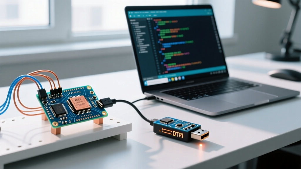
For classic boards like the Arduino Uno R3 or Nano, the microcontroller (e.g., ATmega328P) lacks native USB hardware. The IDE for Windows communicates via a USB-to-Serial bridge chip, typically the ATmega16U2, CH340, or CP2102. However, simply sending serial data is not enough; the microcontroller must be forced into its bootloader mode before it will accept new firmware.
The 0.1µF Capacitor Reset Trick
The IDE achieves this reset using the DTR (Data Terminal Ready) control line of the RS-232/UART protocol. When the Windows IDE opens the serial port to begin uploading, it momentarily asserts the DTR line low. On the PCB, this DTR pin is routed through a 0.1µF (100 nF) capacitor directly to the microcontroller's RESET pin.
- Normal Operation: The capacitor blocks DC current, keeping the RESET pin high via a 10kΩ pull-up resistor.
- Upload Initiation: The IDE toggles DTR low. The capacitor passes this sudden voltage drop as a brief negative spike, pulling the RESET pin low for just long enough (a few microseconds) to trigger a hardware reset.
- Bootloader Entry: Upon waking from reset, the Optiboot bootloader checks the serial RX pin for a specific synchronization character (STK_GET_SYNC) within the first 250 milliseconds.
Native USB and the 1200 bps CDC Reset Trick
Boards with native USB capabilities, such as the Arduino Leonardo, Micro, or the Nano 33 IoT, do not use a dedicated bridge chip or a DTR capacitor. Instead, they use the USB Communications Device Class (CDC) protocol. But how does the Windows IDE tell the board to enter the bootloader if the USB port is currently busy running user code?
The solution is the 1200 bps CDC Reset Trick. When you initiate an upload, the Arduino IDE for Windows briefly opens the virtual COM port at exactly 1200 baud, then immediately closes it. The microcontroller's firmware monitors the USB baud rate; detecting this specific 1200 bps connection acts as a software interrupt. The MCU immediately disables the USB interface, writes a magic number to a specific RAM address, and triggers a watchdog reset. Upon rebooting, the bootloader sees the magic number, stays in programming mode, and re-enumerates on a different COM port, which the IDE then targets for the actual firmware transfer.
The Application Layer: STK500 and Avrdude
Once the bootloader is active, the IDE delegates the actual firmware transfer to a command-line utility called avrdude. For AVR microcontrollers, avrdude uses the STK500 protocol (specifically STK500v1 for Optiboot and STK500v2 for larger Mega boards).
The STK500 protocol is a simple, packet-based binary protocol operating over UART. A typical upload sequence looks like this:
- Synchronization: Avrdude sends
0x30(STK_GET_SYNC) followed by0x20(SYNC_CRC_EOP). The bootloader must reply with0x14(STK_INSYNC) and0x10(STK_OK). - Hardware Check: Avrdude requests the software/hardware version and device signature to ensure the correct chip is connected.
- Page Erase & Write: The binary hex file is broken down into pages (usually 128 or 256 bytes). Avrdude sends load address commands, followed by data packets, and finally a write page command.
- Verification: Avrdude reads the flash memory back over the serial link to verify the checksum matches the local file.
Expert Insight: In Windows, the Arduino IDE stores these toolchains deep within the AppData directory. You can find the exact avrdude configuration and executables at
C:\Users\[YourUsername]\AppData\Local\Arduino15\packages\arduino\tools\avrdude\. Modifying theavrdude.conffile here allows you to add custom signatures for clone microcontrollers, such as the ATmega328PB.
ARM Boards and the SAM-BA Protocol
When you move to 32-bit ARM boards like the Arduino Zero or Due, the STK500 protocol is abandoned in favor of SAM-BA (Serial ATMEL Bootloader Assistant) or the Bossac utility. SAM-BA operates over the USB CDC interface and utilizes the XMODEM protocol or raw binary streaming for high-speed flash writing. Unlike the 115200 baud limit of classic AVRs, SAM-BA leverages the full bandwidth of USB 2.0 Full-Speed (12 Mbps), allowing megabyte-sized sketches to upload in seconds rather than minutes.
Protocol Comparison Matrix: Bootloaders in the Ecosystem
| Bootloader / Tool | Protocol Standard | Default Baud Rate | Reset Mechanism | Common Target Boards |
|---|---|---|---|---|
| Optiboot | STK500v1 | 115200 bps | DTR via 0.1µF Cap | Uno R3, Nano, Pro Mini |
| ATmegaBOOT | STK500v1 | 57600 bps | DTR via 0.1µF Cap | Arduino Diecimila, older Duemilanove |
| STK500v2 | STK500v2 | 115200 bps | DTR via 0.1µF Cap | Arduino Mega 2560 |
| Caterina | AVR109 | 57600 bps | 1200 bps CDC Trick | Leonardo, Micro, Pro Micro |
| Bossac / SAM-BA | SAM-BA / XMODEM | USB Native (921600+) | 1200 bps CDC Trick | Zero, Due, Nano 33 IoT |
Windows-Specific Troubleshooting & USB Latency
Windows handles USB-to-Serial buffering differently than Linux or macOS, which frequently leads to protocol timeout errors like stk500_recv(): programmer is not responding. The FTDI or CH340 drivers on Windows often employ a 'Latency Timer' to batch serial data, artificially delaying the bootloader's response by up to 16 milliseconds. Since the STK500 protocol expects responses within a strict window, this buffering causes the upload to fail.
Step-by-Step: Fixing Windows Latency Timer Issues
- Open the Windows Device Manager and expand 'Ports (COM & LPT)'.
- Right-click your Arduino's COM port and select Properties.
- Navigate to the Port Settings tab and click Advanced.
- Locate the Latency Timer setting. By default, Windows sets this to 16.
- Change the value to 1 millisecond and click OK.
- Restart the Arduino IDE 2.x to clear the serial cache.
Furthermore, if you are using a clone board with a CH340 chip, Windows 11 and Windows 10 updates frequently overwrite the working manufacturer driver with a broken generic Microsoft driver. Always ensure you have the latest signed drivers directly from the silicon vendor, such as the Silicon Labs CP210x VCP drivers or the official WCH CH341SER executables, rather than relying on Windows Update.
Frequently Asked Questions (FAQ)
Why does my Arduino COM port change numbers during upload?
This occurs exclusively on Native USB boards (Leonardo, Micro). The user sketch and the bootloader present different USB descriptors to the Windows Plug and Play manager. When the 1200 bps reset trick triggers the bootloader, Windows sees a 'new' device and assigns it the next available COM port number. The Arduino IDE for Windows is programmed to detect this enumeration event and automatically switch its target port mid-upload.
Can I use the Arduino IDE to upload code via an ISP programmer instead of serial protocols?
Yes. By selecting 'Upload Using Programmer' under the Sketch menu, the IDE bypasses the serial bootloader entirely. It invokes avrdude with the -c flag targeting protocols like USBasp, STK500v2 (via AVRISP mkII), or wiring. Note that this method overwrites the bootloader, meaning you will need an external ISP programmer to restore serial upload capabilities later.