
The Infinity Symbol: More Than Just Branding
In the sprawling ecosystem of open-source hardware, the Arduino IDE logo—the iconic teardrop-shaped infinity loop—serves as a critical trust anchor. While most makers view it merely as a splash screen graphic or a PCB silkscreen, senior embedded engineers recognize it as a visual shorthand for a specific, guaranteed communication architecture. As of 2026, with the widespread adoption of Arduino IDE 2.3.x and the Renesas-based Uno R4 series, understanding what this logo represents (and what its absence implies) is the first step in establishing a bulletproof serial communication setup.
When you download software bearing the genuine logo from the Official Arduino Software Page, you are not just getting a code editor; you are acquiring a meticulously maintained communication stack that handles CMSIS-DAP debugging, native CDC-ACM USB protocols, and automated board manager JSON parsing. Conversely, encountering a corrupted, slightly off-color, or missing logo often signals a clone board or a third-party IDE wrapper, both of which require entirely different driver configurations and serial handshake protocols.
Software Authenticity: Avoiding the 'Fake IDE' Trap
A common pitfall for beginners is downloading a counterfeit IDE from SEO-optimized spam sites. These sites illegally host the Arduino IDE logo to trick users into downloading adware-laden wrappers or severely outdated 1.8.x legacy forks. These fake environments often lack the modern Serial Plotter, fail to support the Arduino Cloud IoT communication protocols, and bundle malicious USB drivers that can intercept your serial data.
⚠️ Security & Stability Warning: Always verify the digital signature of your IDE installer. The genuine Arduino IDE 2.x installer is signed by Arduino LLC. If your operating system flags the publisher as 'Unknown' or a third-party marketing firm, abort the installation immediately to protect your local network and serial communication ports.
Hardware Communication: Official Boards vs. Clones
The presence of the logo on the physical PCB dictates your underlying USB-to-Serial bridge architecture. Genuine boards bearing the authentic logo utilize high-quality, native USB communication microcontrollers, while clones substitute these with cheaper alternatives to cut costs. This substitution fundamentally changes how your computer's operating system enumerates the COM port.
Communication Stack Comparison Matrix
| Feature | Official Board (Genuine Logo) | Clone Board (Faux/Missing Logo) |
|---|---|---|
| USB-UART IC | ATmega16U2 (Uno R3) / Renesas RA4M1 (Uno R4) | WCH CH340G / CP2102 / FT232RL (often counterfeit) |
| OS Driver Requirement | Native CDC-ACM (Plug-and-Play on Win/Mac/Linux) | Requires manual CH341SER.EXE or VCP driver installation |
| Max Reliable Baud Rate | 2,000,000 bps (Hardware UART limits) | 115,200 bps (Practical limit for cheap CH340 clones) |
| Auto-Reset Circuit | Precision 100nF capacitor on DTR line | Often missing or poor-tolerance, requiring manual reset |
| VID / PID (USB Hex) | 2341 / 0043 (or 006D for R4) | 1A86 / 7523 (CH340) or 10C4 / EA60 (CP2102) |
The Auto-Reset Circuit: The Secret to Seamless Uploads
One of the most vital, yet least understood, communication features tied to genuine Arduino hardware is the DTR (Data Terminal Ready) auto-reset circuit. When you click 'Upload' in the IDE, the software opens the serial port. According to the SparkFun Serial Communication Tutorial, opening the port causes the USB-UART bridge to momentarily assert the DTR line LOW.
On a genuine board, a 100nF coupling capacitor translates this LOW signal into a brief negative pulse directly on the main microcontroller's RESET pin. This forces the chip into the bootloader, ready to receive the new hex file via UART. On ultra-cheap clones lacking the genuine logo and quality control, this capacitor is frequently omitted or replaced with a 10nF cap that fails to trigger the reset threshold. The Symptom: The IDE compiles successfully, but hangs on 'Uploading...' until it times out. The Fix: You must manually press and release the physical RESET button on the clone board the exact millisecond the IDE finishes compiling and begins the upload phase.
Step-by-Step: Establishing Reliable Serial Communication in IDE 2.x
Assuming you have verified your software via the official Arduino IDE logo and installed the correct drivers for your specific hardware, follow this optimized setup for serial telemetry:
- Initialize Serial in Code: Always use
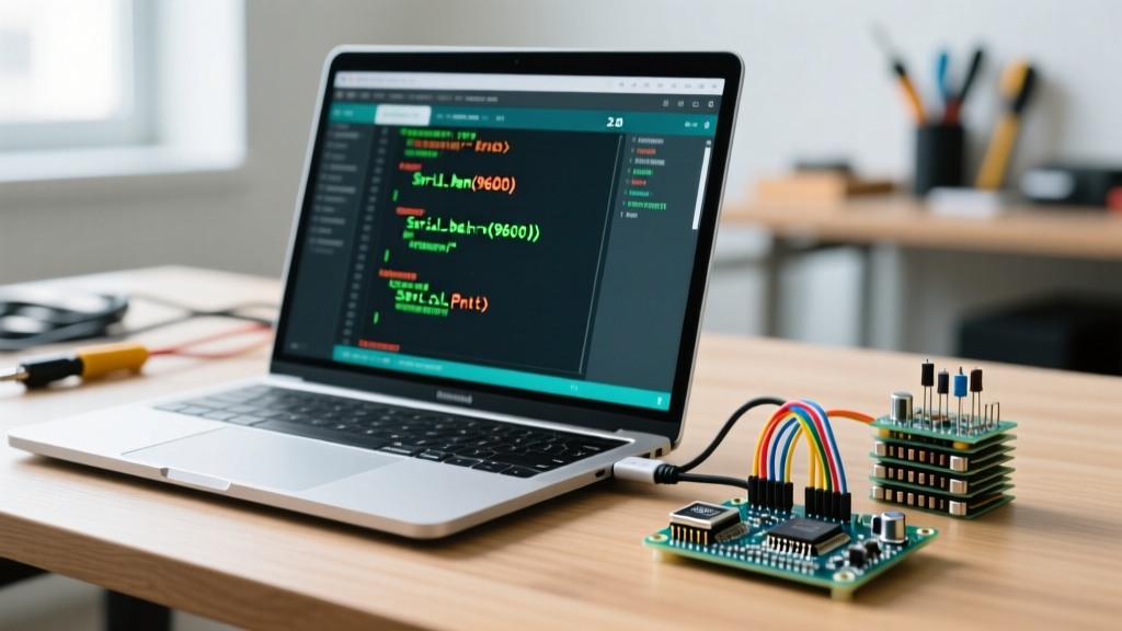
Serial.begin(115200);in yoursetup()loop. While 9600 was the historical standard, 115200 bps is the modern baseline for 2026 IoT telemetry, preventing buffer overflows when streaming sensor arrays. - Implement Handshaking: Add
while (!Serial) { delay(10); }immediately afterSerial.begin(). This is mandatory for native USB boards (like the Leonardo or Uno R4) to prevent the MCU from executing code before the host PC's COM port is fully enumerated. - Open the Serial Monitor: Use the shortcut
Ctrl + Shift + M(orCmd + Shift + Mon macOS) to open the integrated monitor in the bottom panel. - Configure Line Endings: Set the dropdown to 'Both NL & CR' if you are sending AT-commands to external WiFi/Cellular modules (like the SIM7600 or ESP-01), as these modems strictly require Carriage Return + Line Feed terminators.
- Enable Timestamps: Click the clock icon in the Serial Monitor toolbar. This prepends a millisecond-precision timestamp to every incoming packet, crucial for debugging I2C/SPI latency issues via serial printouts.
OS-Level Troubleshooting: When the Port is Greyed Out
If your board is plugged in but the 'Select Board and Port' menu shows a greyed-out COM port, the communication stack has failed at the OS level. Here is how to resolve this based on your hardware's origin:
For Genuine Boards (Native CDC-ACM)
On Linux, genuine boards sometimes lack the default permissions to allow non-root users to access the /dev/ttyACM0 port. You must add your user to the dialout group:
sudo usermod -a -G dialout $USERNote: A full system reboot is required for group changes to take effect.
For Clone Boards (CH340G / CP2102)
Windows 11 and modern macOS versions occasionally block unsigned or outdated CH340 drivers. Download the latest signed CH341SER executable directly from the WCH (Nanjing Qinheng) official repository, not from third-party 'driver update' sites. After installation, open Windows Device Manager, expand 'Ports (COM & LPT)', and verify the device reads USB-SERIAL CH340 (COMx). If it shows a yellow exclamation mark (Code 10), the USB cable you are using is likely a 'charge-only' cable lacking the D+ and D- data lines. Swap to a verified data-sync cable.
Frequently Asked Questions (FAQ)
Does the Arduino IDE logo guarantee the board is made in Italy?
No. The logo signifies adherence to Arduino's open-source hardware (OSH) specifications and licensing. While early genuine boards were manufactured exclusively in Italy, modern genuine Arduino boards are assembled globally, including facilities in China and Vietnam, provided they pass Arduino LLC's strict quality control and use the licensed ATmega16U2/RA4M1 communication bridges.
Why does my clone board work on my PC but not my Raspberry Pi?
Raspberry Pi OS (Linux) includes native CDC-ACM drivers for genuine Arduino hardware out-of-the-box. However, the kernel module for the CH340 (ch341.ko) might be blacklisted or missing on minimal Pi OS builds. You may need to manually compile the CH340 driver via DKMS or write a custom udev rule assigning the correct VID/PID (1A86:7523) to the dialout group.
Can I use the Serial Plotter with clone boards?
Yes. The Serial Plotter in IDE 2.x parses standard CSV-formatted strings (e.g., Serial.println("Temp:24.5,Hum:60");). However, because clone CH340 chips often struggle with sustained baud rates above 115200, high-frequency plotting (e.g., 1000Hz accelerometer data) will result in dropped packets and jagged graphs. For high-speed data visualization, a genuine board with native USB capabilities is strictly required.
For deeper insights into board manager URLs and custom communication cores, always refer to the Arduino IDE v2 Documentation. Understanding the hardware realities behind the software branding is what separates a frustrated hobbyist from a proficient embedded systems engineer.