
The Architecture of I2C: Beyond Just Two Wires
The Inter-Integrated Circuit (I2C) protocol is the undisputed backbone of Arduino sensor networks. Whether you are chaining environmental sensors, OLED displays, or motor drivers, I2C allows multiple peripherals to communicate with a microcontroller using only two shared lines. However, identifying the correct Arduino I2C pins can be surprisingly complex when migrating between board families, dealing with mixed logic levels, or pushing bus speeds beyond standard 100kHz limits.
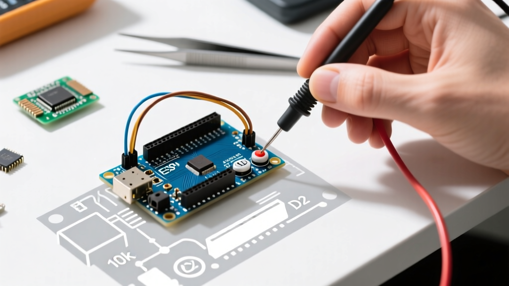
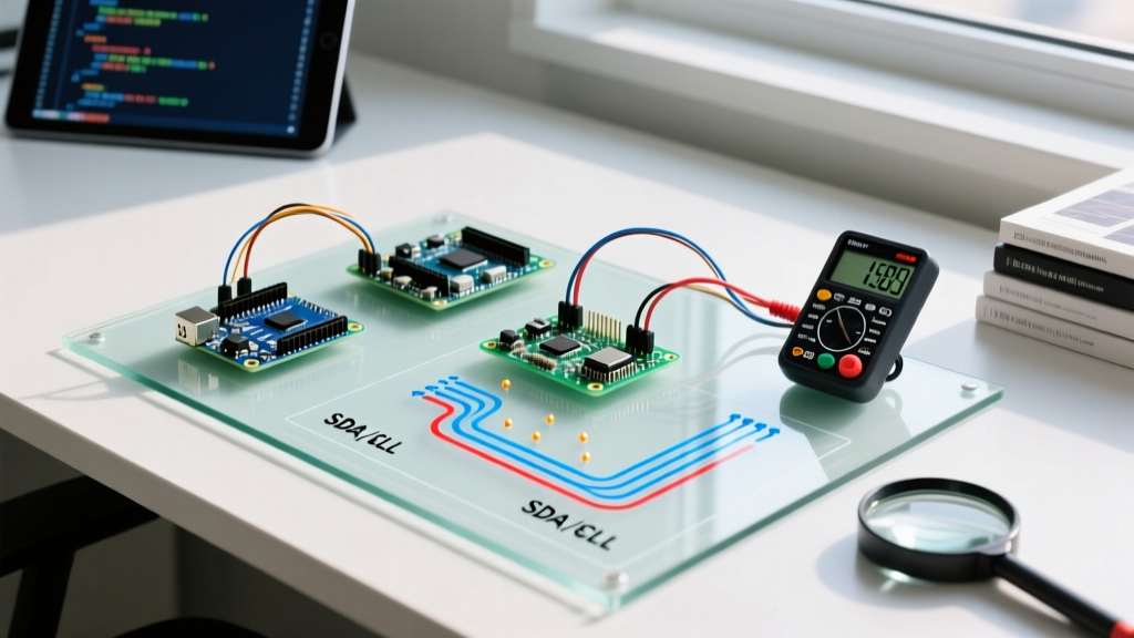
At its core, I2C relies on two open-drain lines: SDA (Serial Data) and SCL (Serial Clock). Because the architecture is open-drain (or open-collector), devices can only pull the line LOW to ground; they cannot drive it HIGH. This necessitates external pull-up resistors to return the bus to a HIGH state. Understanding this hardware reality is the first step to mastering I2C communication and avoiding the dreaded "bus lockup" failures that plague many DIY projects.
Definitive Arduino I2C Pins Matrix
Pinouts vary drastically across the Arduino ecosystem. While older boards mapped I2C to specific analog pins, modern architectures route them through dedicated hardware interrupt headers or specific GPIO matrices. Below is the definitive hardware I2C pin mapping for the most popular boards used in 2026.
| Board Model | SDA Pin | SCL Pin | Native Logic Level | On-Board Pull-ups? |
|---|---|---|---|---|
| Arduino Uno R3 | A4 | A5 | 5.0V | Yes (10kΩ) |
| Arduino Uno R4 WiFi | A4 / Pin 20 | A5 / Pin 21 | 5.0V (RA4M1) / 3.3V (ESP32-S3) | Yes (via RA4M1) |
| Arduino Mega 2560 | 20 | 21 | 5.0V | Yes (10kΩ) |
| Arduino Nano Every | A4 | A5 | 5.0V | Yes (10kΩ) |
| ESP32 DevKit (V1) | GPIO 21 | GPIO 22 | 3.3V | No (External Required) |
| Arduino Nano 33 IoT | A4 | A5 | 3.3V | Yes (via SAMD21) |
Pro-Tip for Uno R4 Users: The Uno R4 WiFi features two separate microcontrollers. The primary Renesas RA4M1 operates at 5V and handles the standard A4/A5 I2C headers. The secondary ESP32-S3 module operates at 3.3V. If you are bypassing the RA4M1 and programming the ESP32 directly via the Arduino IDE, you must use 3.3V logic sensors and route them to the ESP32's native GPIO pins, not the standard 5V SDA/SCL headers.
Hardware vs. Software I2C: When to Use Which
The native Arduino Wire library utilizes the microcontroller's dedicated hardware I2C peripheral, ensuring precise timing and freeing up CPU cycles. However, if your hardware pins are damaged, or you need a secondary I2C bus for a specific isolated sensor, you can use the SoftwareWire library to bit-bang I2C on any digital pins. Software I2C is strictly limited to Standard Mode (100kHz) and is highly susceptible to timing jitter if your sketch utilizes heavy interrupts or delays. Always default to hardware pins unless physically constrained.
Pull-Up Resistor Engineering: The 400pF Rule
The most common cause of I2C failure in advanced projects is incorrect pull-up resistor sizing. According to the NXP I2C Specification (UM10204), the I2C bus has a strict maximum capacitance limit of 400pF for Standard and Fast modes. Every wire, breadboard trace, and sensor pin adds parasitic capacitance to the bus.
If your pull-up resistors are too weak (high resistance), the RC time constant increases, and the SDA/SCL lines cannot reach a valid HIGH logic level before the next clock edge. If they are too strong (low resistance), the current sink required to pull the line LOW exceeds the microcontroller's maximum I_ol (Output Low current) rating, typically 3mA to 20mA depending on the silicon.
Calculating the Minimum Resistor Value
To find the absolute minimum pull-up resistance allowed without violating the I_ol spec, use the following formula:
R_p(min) = (V_cc - V_ol(max)) / I_ol
For a 5V Arduino Uno R3, assuming a maximum V_ol of 0.4V and a conservative I_ol sink limit of 3mA:
R_p(min) = (5.0V - 0.4V) / 0.003A = 1,533 Ω
Therefore, using a 1kΩ pull-up on a 5V bus will over-stress the ATmega328P's internal transistors over time. A standard 4.7kΩ resistor is the industry sweet spot for 100kHz buses under 2 meters in length. For Fast-Mode (400kHz) buses with higher capacitance, dropping to 2.2kΩ is recommended to sharpen the rising edges. You can purchase pre-packaged I2C pull-up resistor networks (like the Adafruit I2C Pull-up Breakout) for around $3.00 to $5.00, saving you from wiring loose through-hole resistors.
Mixing 3.3V and 5V Logic: The BSS138 Solution
A frequent edge case occurs when connecting modern 3.3V sensors (like the BME280 or MPU9250) to a classic 5V Arduino Uno. Directly connecting a 5V SDA line to a 3.3V sensor will eventually destroy the sensor's internal ESD protection diodes due to overvoltage on the I2C pins.
To solve this, you must use a bidirectional logic level converter. Do not use simple resistor voltage dividers; they are unidirectional and will corrupt the open-drain SDA line. Instead, use a level shifter based on the BSS138 N-channel MOSFET. These modules (typically priced between $1.50 and $3.00 on electronics marketplaces) use the MOSFET's gate threshold to safely isolate the 5V and 3.3V domains while preserving the open-drain pull-up architecture on both sides of the bus.
Address Collisions and the TCA9548A Multiplexer
I2C devices communicate via 7-bit or 10-bit hexadecimal addresses. Many popular sensors have hardcoded addresses. For example, the ubiquitous MPU6050 accelerometer is locked to 0x68 (or 0x69 if a specific pin is pulled high). If your robotics project requires three MPU6050 modules for multi-limb kinematics, you will face an address collision.
The most robust hardware solution is the TCA9548A I2C Multiplexer (available from Adafruit or Texas Instruments for roughly $4.50 to $7.00). This IC sits on the main I2C bus and acts as an 8-channel switch. You send a command to the TCA9548A to enable "Channel 1," communicate with the first sensor, switch to "Channel 2," and communicate with the second sensor. The Arduino Wire Library handles this seamlessly by simply writing the channel byte to the multiplexer's address before executing standard sensor reads.
Real-World Troubleshooting Workflow
When your I2C bus fails, avoid blindly rewriting code. Follow this systematic hardware-first diagnostic flow:
- Run the I2C Scanner Sketch: Load the standard
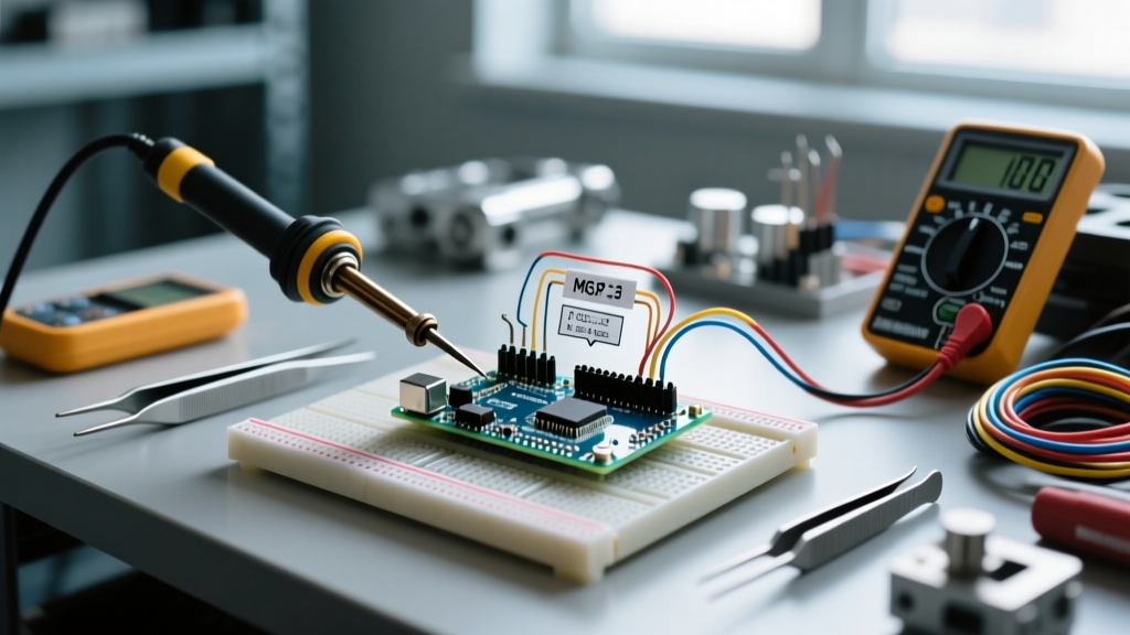
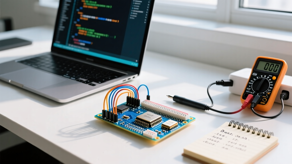
i2c_scannersketch from the Arduino Playground. If the serial monitor returns "No I2C devices found," you have a physical layer issue (wiring, power, or pull-ups). - Verify Logic Levels with a Multimeter: Measure the DC voltage on the SDA and SCL lines relative to the sensor's ground. An idle I2C bus should read very close to V_cc (e.g., 4.8V or 3.2V). If it reads near 0V, a device is holding the bus LOW (a lockup condition), or your pull-up resistors are missing.
- Check for Clock Stretching Failures: Some sensors (like certain SHT3x humidity modules) utilize clock stretching, holding the SCL line LOW to force the master to wait while they process data. The Arduino hardware I2C peripheral handles this automatically, but SoftwareI2C often times out here. If a sensor hangs, switch to hardware pins.
- Deploy a Logic Analyzer: For intermittent data corruption, connect a $15 USB logic analyzer clone (compatible with Saleae Logic 2 software) to the SDA and SCL lines. Decode the I2C protocol in the software to visually inspect for NACK (Not Acknowledged) bits, which indicate the master is talking to an address that isn't responding.
Frequently Asked Questions
Can I use analog pins as digital I2C pins?
Yes. On boards like the Uno R3 and Nano, A4 and A5 are internally routed to the ATmega's hardware TWI (Two-Wire Interface) peripheral. When the Wire.begin() function is called, the microcontroller automatically reconfigures these pins from analog inputs to digital open-drain I/O. You do not need to call pinMode() for them.
What happens if I completely forget pull-up resistors?
Without pull-ups, the SDA and SCL lines will float. The microcontroller may read random noise as clock pulses or data bits, resulting in phantom addresses, corrupted data payloads, or the internal I2C state machine locking up entirely, requiring a hard power cycle to reset.
How do I increase the I2C clock speed in Arduino?
By default, the Arduino Wire library initializes the bus at 100kHz (Standard Mode). If your sensors support Fast Mode, you can increase the speed to 400kHz by adding Wire.setClock(400000); immediately after Wire.begin();. Note that higher speeds require shorter wires and stronger (lower value) pull-up resistors to maintain signal integrity, as detailed in Texas Instruments Application Note SLVA704 regarding I2C bus capacitance limits.