
Why Pair the ESP32 with Arduino IDE?
The ESP32 is a powerhouse in the microcontroller world, offering dual-core processing at 240MHz, integrated Wi-Fi, and Bluetooth capabilities. However, Espressif’s native ESP-IDF framework has a steep learning curve. By programming the ESP32 with Arduino IDE, beginners can leverage the familiar, simplified C++ syntax and vast library ecosystem of Arduino while utilizing the raw hardware performance of the ESP32. As of 2026, the Arduino IDE 2.3+ and the official Espressif Arduino Core v3.x provide a remarkably stable, professional-grade development environment for these chips.
Hardware Checklist: Choosing Your ESP32 Dev Board
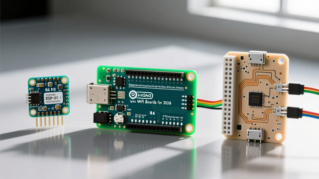
Before writing code, you need the right hardware. While the original ESP32-WROOM-32 remains popular, the ecosystem has expanded. Here is a breakdown of the most common development boards you will encounter, along with their 2026 market pricing:
- NodeMCU-32S (ESP32-WROOM-32): The classic beginner board. Features 30 pins, dual-core 240MHz, and 4MB flash. Usually equipped with a Micro-USB port. Price: $5.00 - $7.00.
- ESP32-S3-DevKitC-1: The modern upgrade. Includes native USB support (no serial-to-USB chip needed), AI vector instructions, and 8MB+ flash/PSRAM. Uses USB-C. Price: $8.00 - $11.00.
- ESP32-C3-DevKitM-1: A single-core RISC-V alternative. Excellent for low-power IoT nodes where dual-core processing is overkill. Price: $4.50 - $6.00.
Pro-Tip: For your first project, buy a board with a CP2102 USB-to-UART bridge rather than a CH340. The CP2102 offers more reliable auto-reset circuitry, saving you from manually pressing the BOOT button during every upload.
Step 1: Resolving the USB Driver Bottleneck
The number one reason beginners fail to connect their ESP32 with Arduino IDE is a missing or conflicting USB driver. The IDE cannot talk to the board if the operating system does not recognize the serial bridge chip.
Identifying Your Serial Chip
Plug your board into your PC and open your OS Device Manager (Windows) or System Information (macOS). Look under 'Ports (COM & LPT)' or 'USB Devices'.
- If you see 'Silicon Labs CP210x': You are good to go. Modern Windows 11 and macOS versions include these drivers natively.
- If you see 'USB-Serial CH340' or an 'Unknown Device': You must manually install the CH340 driver. Download the official CH340 driver from the manufacturer (WCH) or a trusted repository, install it, and restart your IDE.
Edge Case Warning: If you have previously installed 3D printer software (like older versions of Cura) or CNC controllers, they often bundle outdated CH340 drivers that conflict with Arduino IDE 2.3+. Uninstall the old driver via Device Manager before installing the latest version.
Step 2: Configuring Arduino IDE for Espressif
The Arduino IDE does not support the ESP32 out of the box. You must add the Espressif board manager index. For comprehensive details on the core architecture, refer to the official arduino-esp32 GitHub repository.
- Open Arduino IDE and navigate to File > Preferences (or Arduino IDE > Settings on macOS).
- Locate the 'Additional boards manager URLs' field.
- Paste the following exact URL:
https://raw.githubusercontent.com/espressif/arduino-esp32/gh-pages/package_esp32_index.json - Click 'OK'. Next, open the Boards Manager from the left-hand sidebar.
- Search for 'esp32' and install the package named esp32 by Espressif Systems. Ensure you install the latest v3.x release for 2026 compatibility.
Step 3: Your First Upload and the 'BOOT' Button Quirk
Let us verify the toolchain with a basic sketch. Go to Tools > Board > esp32 and select your specific model (e.g., 'NodeMCU-32S' or 'ESP32S3 Dev Module'). Select the correct COM port.
Load the 'Blink' example. However, note that while older ESP32 boards use GPIO 2 for the onboard LED, the newer ESP32-S3 uses GPIO 48. Adjust the code accordingly:
#define LED_BUILTIN 2 // Change to 48 for ESP32-S3

void setup() {
  pinMode(LED_BUILTIN, OUTPUT);
}

void loop() {
  digitalWrite(LED_BUILTIN, HIGH);
  delay(1000);
  digitalWrite(LED_BUILTIN, LOW);
  delay(1000);
}
The 'Timed Out' Error Fix
When you click Upload, you might encounter this dreaded error:
'A fatal error occurred: Failed to connect to ESP32: Timed out waiting for packet header'
The Fix: The ESP32 requires GPIO 0 to be pulled LOW during boot to enter the serial bootloader. Many cheap clone boards have faulty auto-reset circuits. When the IDE outputs 'Connecting...', press and hold the physical BOOT button on the ESP32 board. Release it once the IDE says 'Writing at 0x00010000... (10%)'. The upload will complete successfully.
Critical Hardware Quirks Every Beginner Must Know
Programming the ESP32 with Arduino IDE abstracts the software, but it does not change the physical silicon constraints. Ignoring these hardware quirks will lead to hours of frustrating debugging.
1. The ADC2 and Wi-Fi Conflict
The ESP32 features two Analog-to-Digital Converters: ADC1 and ADC2. If your project uses Wi-Fi, you cannot use ADC2 pins. The Wi-Fi radio monopolizes the ADC2 hardware interrupt. If you attempt to read analog sensors on GPIO 0, 2, 4, 12, 13, 14, 15, 25, 26, or 27 while Wi-Fi is active, the analogRead() function will return erratic values or fail silently. Always route analog sensors to ADC1 pins (GPIO 32, 33, 34, 35, 36, 39).
2. Strapping Pins and Boot Failures
According to the official Espressif GPIO documentation, certain pins are 'strapping pins' sampled during power-on to determine the boot mode. These include GPIO 0, 2, 12, and 15.
- GPIO 0: Must be HIGH to boot normally. If you wire a button to GPIO 0 that pulls it LOW on startup, the ESP32 will enter bootloader mode and your code will not run.
- GPIO 12: Determines flash voltage. If pulled HIGH unexpectedly, the board may brownout and boot-loop.
- Best Practice: Avoid using strapping pins for external peripherals that might alter their state during the 500ms power-on window.
ESP32 Upload Troubleshooting Matrix
Use this diagnostic table when your ESP32 with Arduino setup refuses to compile or upload.
| Error Message / Symptom | Root Cause | Actionable Solution |
|---|---|---|
| 'Board not found' / Port greyed out | Missing USB driver or bad cable. | Install CH340/CP2102 drivers. Swap to a data-capable USB cable (many cheap cables are power-only). |
| 'Timed out waiting for packet header' | Auto-reset circuit failure. | Hold the physical BOOT button when 'Connecting...' appears. Release when writing starts. |
| 'Brownout detector was triggered' | Insufficient current from USB port. | Plug into a dedicated 5V/2A wall adapter instead of a PC USB hub. The ESP32 can spike to 500mA during Wi-Fi transmission. |
| Compilation Error: 'Wire.h not found' | Core installation corruption. | Delete the 'esp32' folder in your AppData/Local/Arduino15/packages directory and reinstall via Boards Manager. |
| Random reboots during Wi-Fi init | Power supply ripple or missing capacitor. | Solder a 100µF electrolytic capacitor across the 3.3V and GND pins on the dev board to smooth voltage spikes. |
Next Steps for Your ESP32 Journey
Successfully pairing the ESP32 with Arduino IDE opens the door to advanced IoT projects. Once you have mastered the basic blink and serial monitor, explore the WiFi.h and WebServer.h libraries to host local web servers. For deeper insights into network protocols and power management, consult the Arduino official documentation and Espressif's technical reference manuals. Remember to always respect the hardware constraints—especially regarding ADC pin selection and power delivery—to ensure your projects remain stable in the real world.