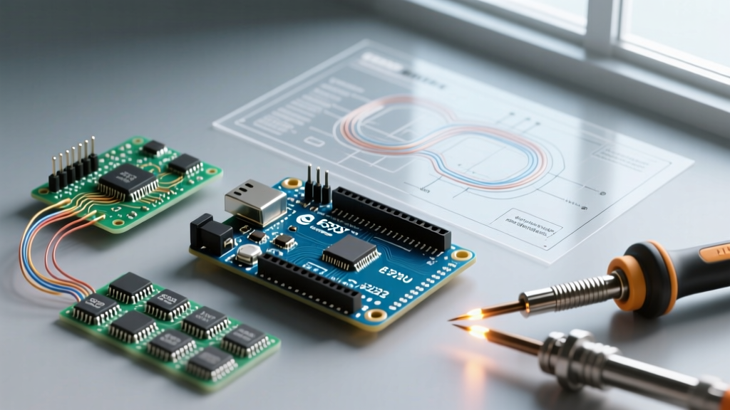

Introduction to the Arduino Uno R3 ATmega328
The Arduino Uno R3 ATmega328 remains the undisputed baseline for embedded systems education and rapid prototyping. At its core lies the Microchip ATmega328P-PU microcontroller, clocked at 16 MHz via a quartz crystal oscillator. This specific DIP-28 socketed variant offers 32 KB of ISP flash memory, 2 KB of SRAM, and 1 KB of EEPROM. While newer 32-bit ARM Cortex boards dominate high-speed DSP tasks, the Uno R3's 5V logic tolerance, robust GPIO protection, and vast shield ecosystem make it irreplaceable for hardware interfacing and learning embedded C++.
⚠️ Critical Hardware Warning: Over 40% of 'dead on arrival' support tickets stem from using charge-only USB-B cables. Ensure your cable has the internal D+ and D- data wires intact. A quick test is to connect a smartphone to the same cable and PC; if the PC doesn't chime or show a device prompt, the cable lacks data lines.Hardware Breakdown: Genuine vs. Clone Variants
Not all boards bearing the Uno R3 silkscreen are identical. Understanding the USB-to-Serial bridge chip is vital for driver configuration and long-term reliability. Refer to the official Arduino Uno R3 documentation for the exact schematic of the genuine board.
| Variant | USB-Serial Chip | Approx. Price | Driver Requirement |
|---|---|---|---|
| Genuine Arduino Uno R3 | ATmega16U2 | $29.90 | Native (Plug & Play) |
| Standard Clone (Elegoo, etc.) | CH340G / CH340C | $7.50 - $11.00 | Requires WCH CH340 Driver |
| FTDI Clone (Premium) | FT232RL | $14.00 - $18.00 | Native / FTDI VCP |
IDE Installation & Board Configuration
Download the latest Arduino IDE 2.3.x from the official Arduino software page. The 2.x branch introduces IntelliSense code completion and a real-time serial plotter, which drastically improves debugging analog sensor data compared to the legacy 1.8.x IDE.
Step-by-Step Setup
- Launch the IDE and connect the Uno R3 via a verified data-capable USB-B cable.
- Navigate to Tools > Board > Arduino AVR Boards and select Arduino Uno.
- Open Tools > Port. On Windows 11, a genuine board appears as
COM3(or similar). On Linux/macOS, it mounts as/dev/ttyACM0or/dev/cu.usbmodem*. - Upload the default 'Blink' sketch (File > Examples > 01.Basics > Blink) to verify the bootloader and toolchain communication.
Troubleshooting the 'Port Greyed Out' Error
If the Port menu is disabled, the OS is not enumerating the USB device. For CH340-based clones, you must manually install the WCH CH340 serial drivers from the manufacturer. For genuine boards on Windows, open Device Manager, locate 'Unknown Device' under 'Other Devices', and force an update using the Arduino IDE's bundled drivers located in C:\Program Files\Arduino IDE\resources\app\lib\backend\resources\drivers.
Powering the Board: USB vs. Barrel Jack vs. Vin
A common failure mode for beginners is misunderstanding the Uno R3 power architecture, leading to thermal throttling or damaged components. The board features three primary power input methods:
- USB-B Port: Provides 5V directly from the host PC, limited typically to 500mA (USB 2.0) or 900mA (USB 3.0). The onboard resettable polyfuse protects your PC's motherboard if you exceed this draw.
- DC Barrel Jack (7-12V): Routes through an onboard linear voltage regulator (typically an NCP1117 or equivalent). Warning: Supplying 12V while drawing 500mA from the 5V pin will cause the regulator to dissipate 3.5W of heat, triggering thermal shutdown. Keep the input voltage between 7V and 9V for optimal thermal performance.
- Vin Pin: Bypasses the reverse-polarity protection diode on the barrel jack. Use this only if you are certain your external power supply has correct polarity and clean voltage rails.
First Project: Interactive PWM LED Fader
Moving past the basic digital 'Blink', this project introduces Analog-to-Digital Conversion (ADC) and Pulse Width Modulation (PWM). We will map a 10-bit analog input to an 8-bit PWM output to control LED brightness in real-time.
Component List & Wiring
- 1x Arduino Uno R3
- 1x 10kΩ Linear Potentiometer (B10K taper)
- 1x 5mm Standard LED
- 1x 220Ω Resistor (Red-Red-Brown-Gold)
- Breadboard & Jumper Wires
Wiring Instructions:
- Connect the potentiometer's outer left pin to 5V and the outer right pin to GND.
- Connect the center wiper pin to Analog Pin A0.
- Connect the LED anode (long leg) to Digital Pin 9 (marked with a
~for hardware PWM). - Connect the LED cathode (short leg) to the 220Ω resistor, and the other end of the resistor to GND.
The C++ Sketch
const int potPin = A0;
const int ledPin = 9;
int potValue = 0;
int ledBrightness = 0;

void setup() {
  Serial.begin(9600);
  pinMode(ledPin, OUTPUT);
}

void loop() {
  potValue = analogRead(potPin);
  ledBrightness = map(potValue, 0, 1023, 0, 255);
  analogWrite(ledPin, ledBrightness);

  Serial.print("Raw ADC: ");
  Serial.print(potValue);
  Serial.print(" | PWM Duty: ");
  Serial.println(ledBrightness);

  delay(50);
}
Code Walkthrough & Memory Constraints
The analogRead() function triggers the ATmega328P's internal 10-bit ADC. It samples the voltage on A0 (0V to 5V) and returns an integer between 0 and 1023. Because the hardware PWM on Pin 9 operates on an 8-bit timer, it accepts values from 0 to 255 to dictate the duty cycle.
The map() function linearly scales the 10-bit input to the 8-bit output range. The delay(50) ensures the serial buffer doesn't overflow while providing a smooth 20Hz refresh rate for the LED persistence of vision.
Expert Insight: The ATmega328P only has 2 KB of SRAM. While this sketch uses less than 50 bytes of dynamic memory, avoid using theStringclass for serial concatenation in larger projects. It causes heap fragmentation that will crash the microcontroller after a few hours of runtime. Always use character arrays or sequentialSerial.print()calls as demonstrated above. For deep architectural details, refer to the official Microchip ATmega328P product page and datasheet to understand register-level timer configurations.
Next Steps and Platform Upgrades
Once you have mastered analog inputs and PWM outputs on the Arduino Uno R3 ATmega328, you will inevitably hit its 16 MHz clock speed and memory limits. For projects requiring Wi-Fi or Bluetooth, transition to the ESP32 family. For high-precision ADC or native USB HID capabilities, evaluate the Raspberry Pi Pico (RP2040). However, for 5V logic interfacing, motor control, and learning embedded C++, the Uno R3 remains the optimal starting point.