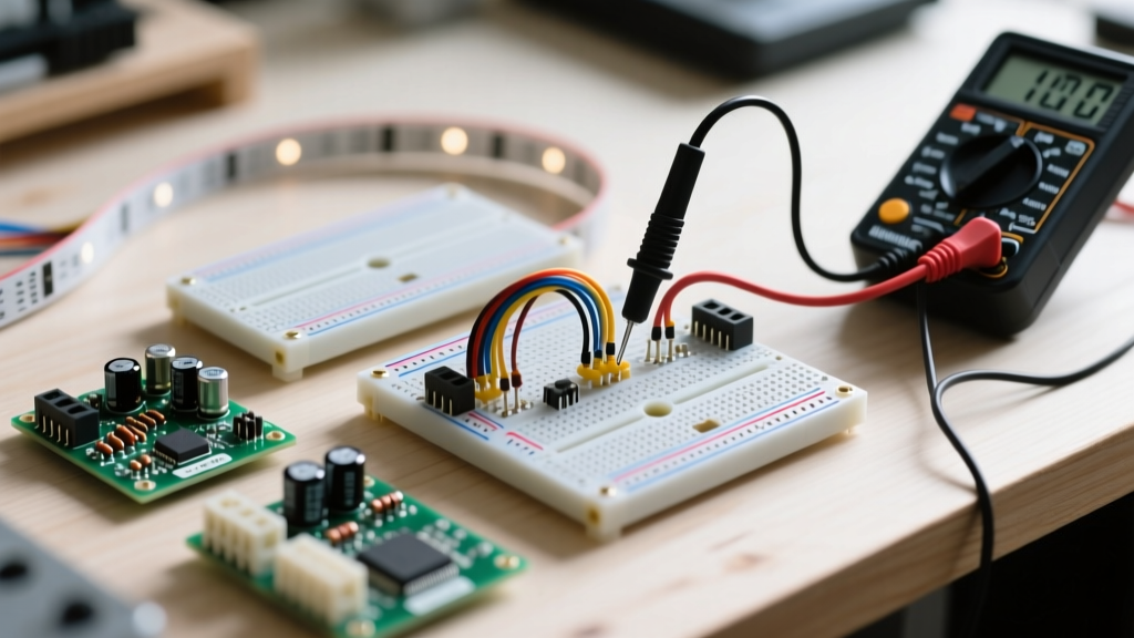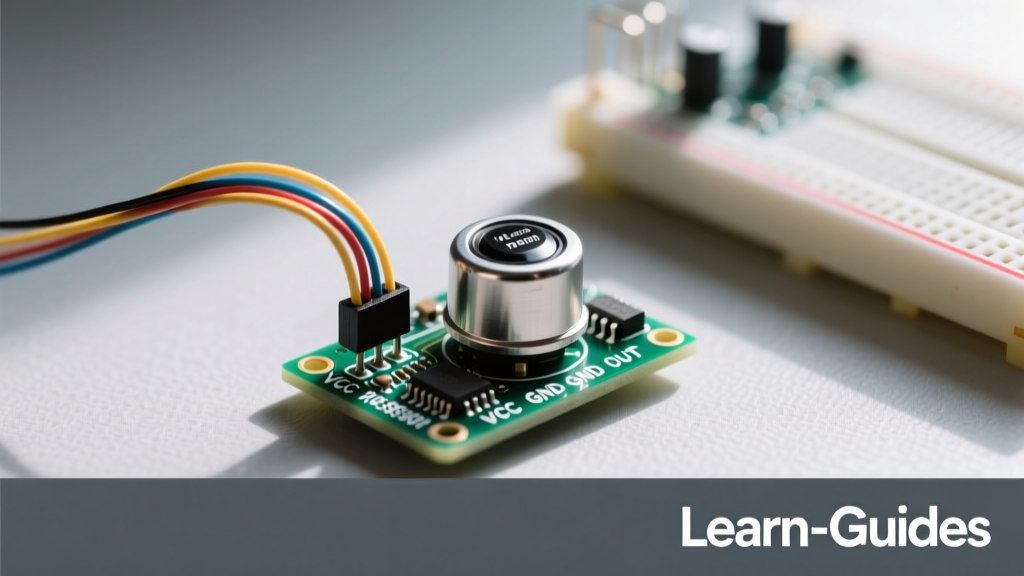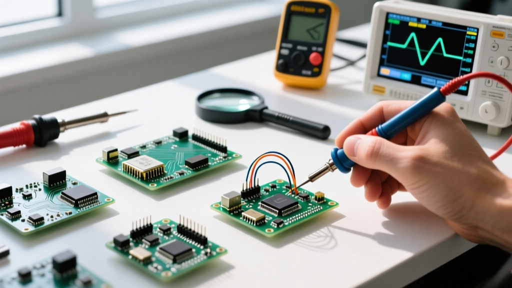

The Anatomy of a WLED-Compatible Bulb
When electronics enthusiasts and smart-home tinkerers refer to WLED bulbs, they are rarely talking about off-the-shelf commercial smart bulbs like the Philips Hue or Wyze. Instead, they are referring to custom-built or retrofitted E27/E14 light fixtures packed with addressable LEDs and driven by an ESP32 or ESP8266 microcontroller running the open-source WLED firmware. Understanding the fundamentals of these bulbs requires bridging the gap between high-voltage AC lighting and low-voltage DC digital logic.
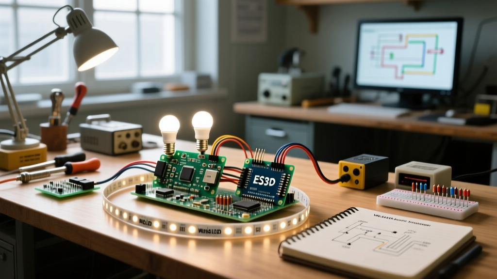
A typical DIY WLED bulb consists of three core subsystems: the addressable LED matrix (often arranged on a flexible PCB or a rigid circular board inside a frosted glass diffuser), the microcontroller unit (MCU) handling the Wi-Fi and data protocols, and a dedicated 5V DC power supply. Unlike standard smart bulbs that use simple PWM dimming on a single RGB chip, WLED bulbs utilize individually addressable pixels, allowing for complex animations, localized dimming, and reactive audio visualizations directly inside the bulb enclosure.
Addressable Chipsets: WS2812B vs. SK6812 RGBW
The most common LED chips found in WLED bulb builds are the WS2812B and the SK6812. Both operate on a single-wire data protocol, but their internal architecture differs significantly:
- WS2812B (RGB): Contains three internal LEDs (Red, Green, Blue). It requires exactly 5V and draws up to 60mA per pixel at full white. The timing protocol is strict, relying on an 800kHz signal where a logic '0' is a 0.4µs high pulse and a logic '1' is a 0.8µs high pulse.
- SK6812 (RGBW): Adds a dedicated white phosphor channel. This is highly preferred for WLED bulbs intended for general room illumination, as the dedicated white diode provides a much higher Color Rendering Index (CRI) and pure white light without the harsh bluish tint of combined RGB channels.
Power Budgeting: The Math Behind the Lumens
The most frequent point of failure in WLED bulb projects is inadequate power delivery. Addressable LEDs are incredibly power-hungry when driven at full brightness. If you are retrofitting an E27 fixture with a 60-LED circular board, you must calculate the maximum current draw to select an appropriate power supply.
According to the Adafruit NeoPixel Überguide, you should always calculate power based on the worst-case scenario (all LEDs displaying pure white at 100% brightness). For a WS2812B bulb, the math is straightforward: 60 LEDs × 0.06 Amps = 3.6 Amps. However, you must add a 20% safety overhead to prevent voltage sag and capacitor aging, bringing the requirement to roughly 4.3 Amps.
| Bulb Configuration | LED Chipset | Max Current (White) | Recommended 5V PSU |
|---|---|---|---|
| Standard E27 (60 LEDs) | WS2812B (RGB) | 3.6 Amps | Mean Well LRS-35-5 (5V 7A) |
| High-Density Globe (144 LEDs) | SK6812 (RGBW) | 8.6 Amps | Mean Well LRS-60-5 (5V 12A) |
| Decorative Edison (30 LEDs) | WS2812B Eco | 1.5 Amps | Standard 5V 3A USB-C Adapter |
Microcontroller Selection and Data Line Integrity
While the ESP8266 (like the Wemos D1 Mini) was the original darling of the WLED community, modern WLED bulb builds heavily favor the ESP32. The ESP32 offers dual-core processing, more stable Wi-Fi, and crucially, hardware I2S and SPI DMA pins. This allows the microcontroller to push the 800kHz data stream to the LEDs without being interrupted by Wi-Fi background tasks, which can cause visible flickering or "tearing" in the bulb's animations.
The 3.3V to 5V Logic Level Shifting Problem
One of the most misunderstood fundamentals in WLED wiring is logic level voltage. The ESP32 operates at 3.3V logic. However, the WS2812B data sheet specifies that the Data In (DI) pin requires a logic high voltage of at least 0.7 × VCC. If you are powering the bulb's LEDs with 5V, the data pin expects a minimum of 3.5V to reliably register a '1'.
Feeding 3.3V directly into a 5V WS2812B chain places the signal in an undefined threshold. This often results in the first LED in the bulb glitching, displaying random colors, or failing to pass the signal to the rest of the bulb. To solve this, professional WLED builds integrate a SN74AHCT125 level shifter on the bulb's internal PCB. This chip safely translates the 3.3V ESP32 GPIO signal into a rock-solid 5V logic signal, ensuring flawless data transmission even over longer internal wire runs.
Retrofitting E27 Fixtures: Thermal and Physical Constraints
Building a WLED bulb is not just about electronics; it is an exercise in thermal management. Standard SMD 2835 white LEDs used in commercial bulbs are highly efficient. Addressable WS2812B and SK6812 chips, however, contain internal logic controllers and three separate diodes per pixel, generating significant heat.
Expert Thermal Tip: Never enclose a high-density addressable LED matrix inside a sealed glass or plastic bulb without a thermal pathway. At 60% brightness, a 60-LED WLED bulb can generate enough heat to exceed the 85°C maximum junction temperature of the internal ICs, leading to permanent color-shifting or catastrophic thermal failure. Always use aluminum-core PCBs or attach the LED ring to an aluminum heat sink inside the bulb base.
If you are retrofitting a vintage glass globe, consider using "Eco" versions of the WS2812B, which draw roughly 30mA per pixel instead of 60mA, cutting the thermal output in half while retaining sufficient luminance for diffused accent lighting.
Diagnosing the "White Flash of Death" and Signal Degradation
When powering up a newly assembled WLED bulb, builders frequently encounter two specific failure modes. Understanding the electrical reasons behind them is crucial for reliable operation.
1. The White Flash of Death (WFD)
If you are using an ESP8266, you may notice the bulb flashing bright white the moment power is applied, before the WLED firmware even boots. This happens because the ESP8266's GPIO1 and GPIO2 pins are used for boot-strapping and serial TX. During the boot sequence, these pins fluctuate wildly, sending garbage data to the LED's DI pin, which the LEDs interpret as a command to turn on full white. To prevent this in a WLED bulb, always use GPIO4 or GPIO5 for your data line, or migrate to an ESP32 where boot-pin behavior is more predictable and isolated from standard user GPIOs.
2. Signal Degradation and the 330Ω Resistor
High-frequency 800kHz square waves are highly susceptible to inductive ringing and capacitive loading, especially when the data wire must travel from the bulb's screw base up to the LED matrix at the top of the globe. To protect the first LED's DI pin from voltage spikes and to dampen signal ringing, it is a fundamental best practice to solder a 330-ohm to 470-ohm resistor directly inline with the data wire, as close to the first LED's DI pad as possible. Furthermore, a 1000µF electrolytic capacitor placed across the 5V and GND terminals at the base of the bulb acts as a local energy reservoir, absorbing the massive inrush current when the bulb transitions from black to bright white, preventing the ESP32 from browning out and rebooting.