
The High-Stakes Reality of Schematic Misinterpretation
In electrical engineering and DIY electronics, schematics are the definitive blueprint for both functionality and safety. While misreading a resistor value might result in a non-functional LED, misinterpreting critical electronic components symbols related to grounding, polarization, and isolation can lead to catastrophic thermal events, equipment destruction, or lethal electric shock. According to OSHA Electrical Safety Guidelines, improper wiring and failure to adhere to isolation boundaries are leading causes of workplace electrical incidents.
This guide moves beyond basic component identification. We will dissect the specific electronic components symbols that dictate safety parameters, explore the physics of their failure modes when ignored, and establish a rigorous pre-power verification protocol for 2026 and beyond.
Critical Safety Electronic Components Symbols Decoded
Standardization bodies like the IEC (International Electrotechnical Commission) maintain the IEC 60617 standard for schematic symbols. Understanding the nuanced differences between visually similar symbols is the first line of defense against hardware failure.
1. Grounding Variations: Earth vs. Chassis vs. Signal
Confusing ground symbols is the most common cause of ground loops, noise injection, and severe shock hazards in mixed-voltage systems. The IEC 60617 standard defines distinct symbols for different ground potentials.
| Symbol Type | Visual Description (IEC 60617) | Safety & Functional Purpose | Failure Mode if Miswired |
|---|---|---|---|
| Earth Ground | Three horizontal lines of decreasing width, or a single line with three downward arrows. | Physical connection to the earth via a grounding rod. Provides a safe path for fault currents to trip breakers. | Lethal shock hazard if mains fault occurs and chassis becomes energized without a low-impedance earth path. |
| Chassis Ground | A single horizontal line with three diagonal lines branching downward at 45 degrees. | Connection to the metal enclosure. Used for EMI shielding and physical safety bonding. | EMI radiation failures; chassis can float to dangerous AC potentials if not bonded to Earth Ground. |
| Signal Ground | A simple downward-pointing triangle or a single horizontal line. | The 0V reference point for low-voltage DC logic and analog signals. | Severe ground loops, 50/60Hz mains hum in audio, and erratic microcontroller resets. |
2. Polarized vs. Non-Polarized Capacitors
The symbol for a non-polarized capacitor consists of two parallel, straight lines. However, polarized capacitors (electrolytic and tantalum) feature one curved line or a distinct '+' polarity marker. Ignoring this distinction is not merely a functional error; it is a severe fire hazard.
- Aluminum Electrolytic Failure: Reversing polarity on a standard aluminum electrolytic capacitor causes the internal dielectric oxide layer to break down. This leads to rapid electrolysis, gas generation, and eventually a violent venting of the pressure relief plug, spraying hot, corrosive electrolyte across the PCB.
- Tantalum Capacitor Thermal Runaway: Tantalum capacitors (often denoted by a specific rectangular block symbol with a polarity bar) are notoriously unforgiving. If a 16V 100µF KEMET T491 series tantalum capacitor is installed backward, it does not just vent; it enters a thermal runaway state. Internal temperatures can exceed 500°C in milliseconds, resulting in a blinding flash, ignition of the FR4 PCB substrate, and the ejection of molten metal.
3. Isolation Boundaries and Optocouplers
When dealing with mains AC to DC conversion, the schematic will feature an optocoupler (e.g., the symbol for a phototransistor with inward-pointing light arrows) or a pulse transformer. Crucially, safety schematics will draw a dashed or solid thick line bisecting the component. This represents the galvanic isolation barrier.
Engineering Insight: The isolation symbol on the schematic dictates physical PCB layout rules. For a 3kVrms isolation requirement (common in medical and industrial power supplies), the physical 'creepage' distance on the PCB surface must be at least 8mm, and 'clearance' through the air must be 6mm. Routing a ground plane directly beneath this isolation symbol voids the safety certification and creates a lethal shock pathway.
4. Fuses and Circuit Breakers: I²t Ratings
The standard fuse symbol is a rectangle with a line passing through the center. However, safety-critical designs differentiate between fast-acting and time-delay (slow-blow) fuses, often adding a small box or mechanical toggle indicator for breakers. Substituting a fast-blow fuse (like a standard glass 5x20mm) in a circuit with high inrush current (like a toroidal transformer or large switching power supply) will result in nuisance tripping. Conversely, using a slow-blow fuse on a sensitive semiconductor line may allow enough let-through energy (measured in I²t, or Ampere-squared seconds) to vaporize a MOSFET before the fuse clears the fault.
Best Practices for Schematic Verification Before Power-Up
To mitigate the risks associated with misread electronic components symbols, implement this rigorous 'Cold-Testing' protocol before applying power to any newly assembled or modified PCB.
- BOM to Schematic Cross-Reference: Do not rely on silkscreen alone. Silkscreen polarity marks for diodes and electrolytic capacitors are frequently mirrored in CAD libraries. Verify the physical component's cathode band against the schematic's bar symbol using a magnifying loupe.
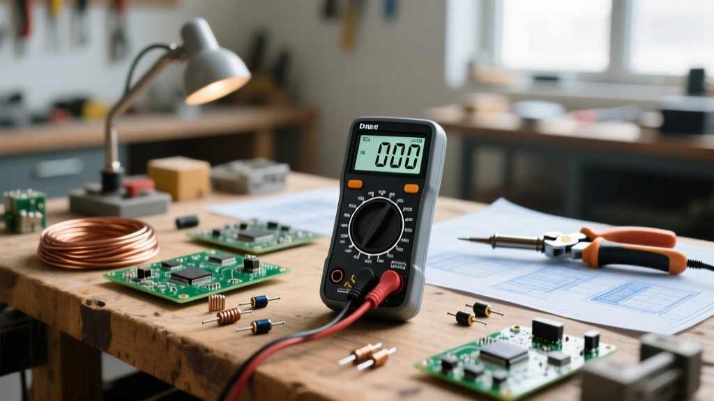
- Dead-Short Verification (VCC to GND): Using a high-precision digital multimeter like the Fluke 87V (retailing around $450 in 2026), set the dial to continuity mode. Place the red probe on the main VCC rail and the black probe on the Signal Ground. A reading of less than 5 ohms indicates a catastrophic short, often caused by a misoriented polarized component or a solder bridge. Note: Large decoupling capacitors may show a brief low-resistance reading as they charge the meter's internal capacitor; wait for the reading to stabilize in the kilo-ohm range.
- Isolation Barrier Hi-Pot Check: For mains-powered devices, use a megohmmeter (Megger) to apply 500V DC between the primary (mains) earth ground and the secondary (low voltage) signal ground. The resistance must read >100 Megohms. If it reads lower, your physical layout has violated the isolation boundary symbol's intent.
- Current-Limited First Power: Never connect a newly built board directly to a stiff power supply or the AC mains. Use a bench power supply with the current limit (OCP) dialed down to 50mA. If the board attempts to draw more due to a reversed polarized symbol error, the supply will drop into constant-current (CC) mode, saving the components from thermal destruction.
Common Edge Cases and Troubleshooting Traps
Even experienced engineers fall victim to legacy symbol conventions that conflict with modern safety standards.
- The 555 Timer Pinout Trap: The schematic symbol for a standard NE555 timer places Pin 1 (GND) at the bottom left and Pin 8 (VCC) at the top right. However, when looking at the physical IC with the notch facing away, the physical pins are mirrored. Inserting the chip backward based on a poorly drawn schematic symbol instantly applies reverse polarity, destroying the silicon junction and causing the IC package to split.
- Op-Amp Power Pins: Many operational amplifier symbols in high-level block diagrams omit the V+ and V- power pins entirely, showing only the inverting, non-inverting, and output pins. This 'hidden pin' convention leads beginners to forget to wire the power rails, resulting in floating inputs, erratic output latching, and potential downstream overvoltage damage to connected microcontrollers.
- PTC Resettable Fuses: The symbol for a Positive Temperature Coefficient (PTC) thermistor often looks identical to a standard resistor with a diagonal line through it. Unlike a standard fuse that opens permanently, a PTC (like the Bourns MF-R series) merely increases its resistance when hot. Troubleshooters often mistake a tripped PTC for a 'bad connection' because it still shows continuity on a standard multimeter, failing to realize it is actively dropping 90% of the circuit voltage in its high-resistance tripped state.
Conclusion
Mastering electronic components symbols is not just an academic exercise in drafting; it is the foundational layer of electrical safety. By strictly adhering to IEC International Standards for symbol interpretation, understanding the violent physics of polarization failures, and enforcing strict cold-testing protocols, you ensure that your designs transition from theoretical schematics to safe, reliable, and robust physical hardware. Always respect the isolation boundary, verify your grounds, and never trust a schematic without empirical verification.