
The Shift from Front Panel to PC Software
When you first unbox a digital storage oscilloscope (DSO) like the popular Rigol DS1054Z or a USB PC oscilloscope like the PicoScope 2204A, the physical knobs or basic bundled software feel sufficient. However, as your DIY electronics projects evolve from simple LED blinking to debugging high-speed I2C, SPI, or CAN bus protocols, relying on a 7-inch front panel screen becomes a severe bottleneck. This is where a dedicated oscilloscope program transforms your workflow.
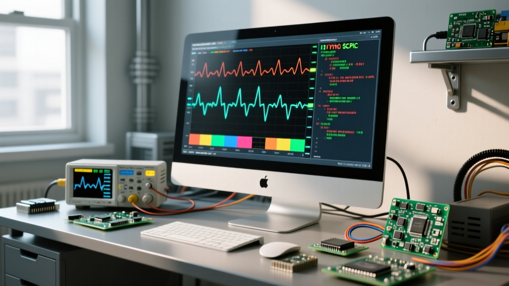
Transitioning to a PC-based oscilloscope program offers three massive advantages: expansive screen real estate for deep memory analysis, advanced serial protocol decoding, and the ability to automate data capture using Python. In this beginner tutorial, we will explore how to choose the right software, configure your first I2C decode, and write a basic automation script to pull waveform data directly into your computer.
Comparing Top Oscilloscope Programs for Beginners
Not all oscilloscope software is created equal. Some programs are designed exclusively for USB tethered hardware, while others act as remote-control dashboards for standalone benchtop units. Below is a comparison of the most common platforms you will encounter in the DIY and entry-level professional space.
| Oscilloscope Program | Compatible Hardware | Cost | Protocol Decoding | Automation API |
|---|---|---|---|---|
| PicoScope 7 | PicoScope USB Series (2000/5000) | Free | Excellent (I2C, SPI, CAN, UART) | C, C#, Python, MATLAB |
| Rigol UltraSigma | Rigol DS/MSO Series | Free | Basic (Requires hardware options) | SCPI via USB/LAN |
| Siglent EasyScopeX | Siglent SDS1000X-E / SDS2000X | Free | Good (Native on most models) | SCPI via LAN/USB |
| LTspice (Simulator) | N/A (Virtual Simulation) | Free | N/A | SPICE Netlists |
For beginners working with microcontrollers like Arduino or ESP32, the PicoScope 7 software is widely considered the gold standard due to its fluid UI and generous free protocol decoding features. If you own a standalone benchtop scope, you will rely on SCPI (Standard Commands for Programmable Instruments) over a USB or LAN connection to interface with custom Python scripts.
Step-by-Step: Decoding I2C with PicoScope 7
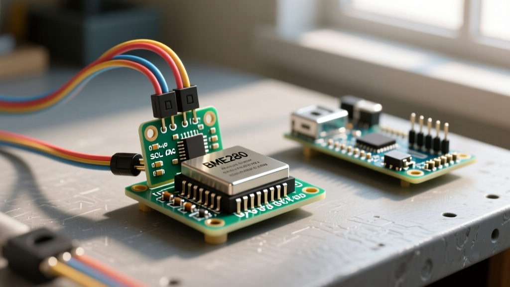
Let us walk through a practical scenario: capturing and decoding an I2C transaction between an ESP32 and a BME280 temperature sensor. We will use a PicoScope 2204A (approx. $169), which features 48 MS (Megasamples) of memory depth in standard mode, allowing you to capture long I2C bursts without dropping samples.
1. Hardware and Probe Setup
Connect Channel A to the SDA (data) line and Channel B to the SCL (clock) line. Ensure your probe attenuation switches are set to 1X, and configure the corresponding 1X setting in the oscilloscope program dropdown menu. I2C operates at 3.3V logic levels, so set your vertical scale to 1V/div to clearly see the digital transitions.
2. Configuring the Trigger
Digital protocols require precise triggering to capture the exact moment communication begins. In the PicoScope program:
- Navigate to the Trigger menu and select Advanced.
- Choose Serial as the trigger type, then select I2C.
- Map SDA to Channel A and SCL to Channel B.
- Set the trigger condition to Start Condition or a specific Device Address (e.g., 0x76 for the BME280).
This ensures the oscilloscope program only captures and displays data when the ESP32 actually initiates a read/write sequence, eliminating minutes of dead air on the bus.
3. Enabling Serial Decoding
Click the Serial Decoding tab at the bottom of the UI. Add a new I2C decoder, map the channels identically to your trigger, and set the serial format to Hexadecimal. The program will now overlay the raw analog square waves with human-readable hex bytes, allowing you to verify if the sensor is returning valid temperature registers.
Automating Your Oscilloscope Program with Python
While GUI programs are excellent for manual debugging, what if you need to run a 24-hour burn-in test on a power supply and log voltage ripple every 60 seconds? This is where programming your oscilloscope via Python becomes invaluable. Most modern benchtop scopes from Rigol and Siglent support SCPI commands over USB-TMC (Test and Measurement Class).
Setting Up the Environment
- Install the NI-VISA driver package from National Instruments to handle low-level USB-TMC communication.
- Install the Python wrapper by running
pip install pyvisa pyvisa-py numpyin your terminal. - Connect your scope via USB and turn on the local interface.
Essential SCPI Commands for Data Extraction
Below is a foundational Python script using the PyVISA library to query the identity of a Rigol DS1054Z and pull raw waveform data from Channel 1 into a NumPy array for further processing.
import pyvisa
import numpy as np

# Initialize the VISA resource manager
rm = pyvisa.ResourceManager()

# Connect to the oscilloscope (Replace with your specific USB VISA string)
scope = rm.open_resource('USB0::0x1AB1::0x04CE::DS1ZA1234567::INSTR')

# Query the device identity to confirm connection
print('Connected to:', scope.query('*IDN?'))

# Set the data source to Channel 1 and request waveform parameters
scope.write(':WAV:SOUR CHAN1')
scope.write(':WAV:MODE NORM')

# Read the raw preamble data to calculate voltage scaling
preamble = scope.query(':WAV:PRE?').split(',')
vertical_gain = float(preamble[7])
vertical_offset = float(preamble[8])

# Fetch the raw byte data and convert to a NumPy array
scope.write(':WAV:DATA?')
raw_data = scope.read_raw()[11:] # Strip the IEEE488 header
waveform = np.frombuffer(raw_data, 'B')

# Convert raw bytes to actual voltage values
voltages = (waveform - 130) * vertical_gain - vertical_offset
print('Captured', len(voltages), 'data points.')
This script bypasses the need to manually save CSV files to a USB thumb drive, enabling real-time statistical analysis, automated pass/fail testing, and direct database logging.
Critical Safety: Preventing USB Ground Loop Failures
When tethering an oscilloscope to a PC via a USB cable, you are electrically bonding the ground planes of both devices. This introduces a severe risk known as a USB ground loop.
Expert Warning: If you are probing a circuit that is referenced to mains earth (like a switching power supply or a motor controller) and your PC is also plugged into a grounded wall outlet, any potential difference between the two grounds will force current directly through the oscilloscope's USB shield. This can instantly destroy the scope's USB controller, fry your PC's motherboard, or cause a localized fire.
To safely use an oscilloscope program with tethered hardware on non-isolated circuits, you must break the ground loop. The most cost-effective solution for beginners is to purchase an ADUM4160-based USB isolator (typically $25 to $40 online). This chip uses magnetic coupling to pass data across an isolation barrier while physically severing the electrical ground connection. Alternatively, running your diagnostic PC on battery power (unplugged from the charger) removes the earth ground reference, though this is less reliable for long-term automated testing.
Summary and Next Steps
Mastering your oscilloscope program bridges the gap between simply viewing a waveform and truly understanding the embedded systems you are building. Start by utilizing PC-based software like PicoScope 7 to leverage your computer's processing power for protocol decoding. Once you are comfortable with the GUI, transition into Python and SCPI automation to build custom test jigs and data loggers. Always prioritize USB isolation when working with mixed-signal or mains-adjacent circuits to protect your valuable test equipment.