
The Hidden Dangers of Incorrect Multimeter Usage
Learning how to use a multimeter safely is not just about getting accurate readings; it is about preventing catastrophic equipment failure, severe burns, or fatal arc flashes. Every year, electricians and DIY hobbyists suffer injuries because they treat a digital multimeter (DMM) as a simple point-and-click device rather than a complex piece of diagnostic test equipment. When a meter is subjected to transient overvoltages or used on the wrong setting, the internal components can vaporize in milliseconds.
According to the Occupational Safety and Health Administration (OSHA), electrical incidents remain a leading cause of workplace fatalities, often stemming from improper testing procedures and the use of uncertified or poorly maintained test instruments. This guide bypasses the basic fluff and dives deep into the physics, safety protocols, and advanced best practices required to operate a multimeter in real-world, high-energy environments.
The 'Amps Jack' Death Trap: A Lethal Common Mistake
The most frequent and dangerous mistake made by both novices and seasoned technicians is leaving the red test probe in the 10A (Amps) current jack and then attempting to measure voltage across a live circuit.
Understanding the Internal Shunt
When you plug your probe into the current jack, you are connecting your meter in parallel with the circuit through an internal shunt resistor. This shunt is designed to have near-zero resistance (often less than 0.01 ohms) so it doesn't affect the current flow. If you touch those probes to a 120V or 240V live source while the meter is in current mode, you are effectively creating a dead short.
Failure Mode Analysis: In a cheap, uncertified meter, this dead short will cause the internal glass fuse to explode, sending shrapnel and plasma out of the meter's casing, potentially causing severe facial burns and blindness. In a high-quality meter, a High Rupturing Capacity (HRC) fuse will safely quench the arc, but the meter will still be destroyed if the fault current exceeds its interrupt rating.
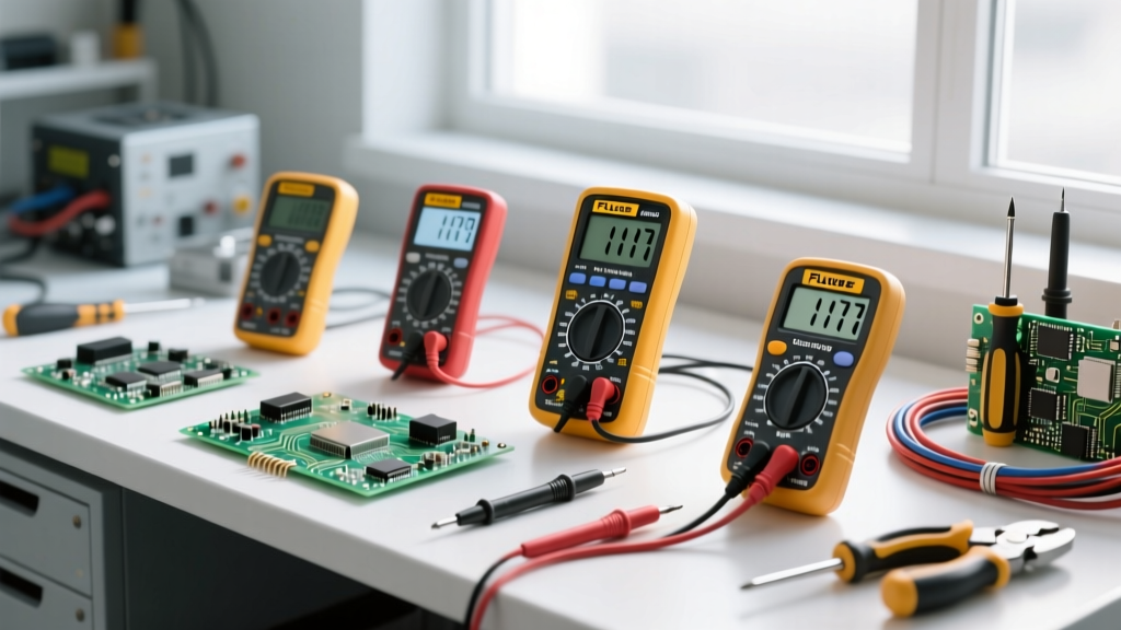
Best Practice: Always develop the habit of physically moving the red probe back to the V/Ω (Voltage/Ohms) jack immediately after taking a current reading. Many modern meters, like the Fluke 117, feature an audible alarm and LCD warning if the dial is turned to voltage while the probe is in the amps jack.
Decoding CAT Ratings: Why Your $15 Meter is a Liability
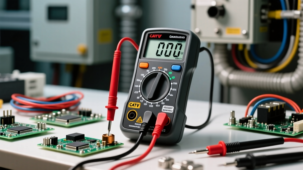
Understanding Measurement Categories (CAT ratings) is non-negotiable for electrical safety. A CAT rating does not just indicate the maximum steady-state voltage the meter can handle; it dictates the meter's ability to survive high-energy transient spikes (like a lightning strike on a power line or a heavy motor switching off) without internal arcing.
| CAT Rating | Environment | Real-World Example | Transient Test Voltage (600V Rating) |
|---|---|---|---|
| CAT I | Electronics | PCB testing, signal generators | 2,500V |
| CAT II | Local Level | Standard wall outlets, appliances | 4,000V |
| CAT III | Distribution | Hardwired equipment, 3-phase panels, lighting | 6,000V |
| CAT IV | Primary Supply | Utility meters, service entrance panels | 8,000V |
As detailed in the Fluke guide to CAT ratings, a CAT III 600V meter is engineered with wider internal creepage and clearance distances, as well as arc-quenching barriers, to withstand an 8,000V transient spike. A cheap, unbranded meter labeled '1000V' but lacking a CAT rating may flash over internally at 2,500V, turning the device into a plasma grenade in your hands.
Step-by-Step: Measuring Live Voltage Safely
When measuring live voltage in a CAT III or CAT IV environment, strict adherence to physical safety protocols is required to mitigate the risk of arc flash and shock.
- Inspect Probes First: Check for cracked insulation, exposed metal, or missing finger guards. Discard damaged probes immediately. Ensure your probes are rated for the same CAT level as your meter.
- Verify the Meter (Live-Dead-Live Test): Test your meter on a known live source (like a proven receptacle tester). Then test the target circuit. Finally, test the known live source again to ensure the meter's internal fuse or battery didn't fail during the measurement.
- The One-Hand Rule: When probing high-voltage panels (e.g., 277V/480V 3-phase), keep one hand in your pocket or behind your back. This prevents a hand-to-hand current path across your heart in the event of a shock.
- Use the Alligator Clip Method: If possible, clip the ground/neutral probe to a known ground, step back, and then apply the hot probe. This removes your hands from the immediate blast radius when the circuit is energized.
Continuity and Resistance: The 'Dead Circuit' Mandate
Measuring resistance or continuity requires the multimeter to output a small internal voltage (usually between 1V and 3V) from its battery to measure the voltage drop across the component.
Never measure resistance on a live circuit. If external voltage is present, it will backfeed into the meter's sensitive ohmmeter circuitry, instantly destroying the internal PTC thermistors and the main ASIC chip. Furthermore, attempting to measure continuity across a capacitor that hasn't been properly discharged will result in a massive current spike that can weld your probe tips to the capacitor terminals and destroy the meter.
Best Practice: Always lock out and tag out (LOTO) the circuit, verify zero energy with a voltage test, and safely discharge all capacitors using a high-wattage bleed resistor before switching your dial to the Ohms (Ω) or Continuity settings.
Advanced Troubleshooting: Ghost Voltages and Input Impedance
When learning how to use a digital multimeter for complex troubleshooting, you will inevitably encounter 'ghost voltages.' These are phantom readings (often 20V to 60V) caused by capacitive coupling between adjacent energized wires and disconnected wires in the same conduit.
Standard DMMs have a high input impedance (typically 10 Megohms) so they don't load the circuit being tested. However, this high impedance makes them act like antennas, picking up stray electromagnetic fields and displaying false voltage readings. This leads to hours of wasted troubleshooting.
The Low Impedance (LoZ) Solution
Premium meters like the Fluke 117 or Brymen BM235 feature a 'LoZ' (Low Impedance) mode. When activated, the meter drops its internal impedance to roughly 3 kilohms. This creates a small load that safely bleeds off the coupled phantom voltage, dropping the display to 0.0V, while still accurately reading true, hard-wired voltage sources. Utilizing LoZ is a critical best practice for industrial electricians troubleshooting motor control circuits and VFDs.
Internal Anatomy: HRC Fuses and Probe Maintenance
A multimeter is only as safe as its internal protection components. High-end meters utilize High Rupturing Capacity (HRC) fuses. Unlike standard glass fuses found in automotive applications, HRC fuses are encased in a sand-filled ceramic body.
If a technician accidentally measures 480V 3-phase power with the probes in the 10A jack, the fault current can exceed 10,000 Amps. A glass fuse would vaporize, ionizing the air inside the meter and creating a sustained, explosive arc. An HRC fuse, however, melts and the surrounding sand instantly turns to glass, quenching the arc and containing the blast entirely within the fuse housing.
Maintenance Checklist:
- Open your meter annually to inspect the HRC fuses for micro-cracks in the ceramic.
- Ensure replacement fuses match the exact interrupt rating (e.g., 100kA at 600V) specified by the manufacturer. Never bypass a blown fuse with a piece of wire or a lower-rated substitute.
- Clean probe tips with isopropyl alcohol to remove oxidation, which can cause erratic contact resistance and inaccurate millivolt readings.
Final Thoughts on Electrical Safety
Mastering how to use a multimeter safely requires a fundamental respect for electrical energy. By investing in properly CAT-rated equipment, strictly adhering to the Live-Dead-Live testing protocol, and understanding the internal limitations of your test gear, you protect both your diagnostic accuracy and your life. For comprehensive standards on electrical workplace safety and arc flash boundaries, always refer to the NFPA 70E Standard for Electrical Safety in the Workplace.