
The Enduring Legacy of the HC-05 Bluetooth Module
In the rapidly evolving landscape of wireless microcontrollers, few components have achieved the cult status of the HC-05 Bluetooth module. Originally designed as a cost-effective Serial Port Profile (SPP) bridge, the HC-05 remains a staple in robotics, automotive telemetry, and DIY home automation. Priced between $3.00 and $5.00 USD on most electronics marketplaces, it offers a master/slave configurable UART bridge that is incredibly easy to deploy—provided you understand its hardware quirks.
This review dissects the HC-05 from the silicon up, exploring its voltage tolerances, the notorious AT command bottleneck, and whether it still holds up against modern BLE alternatives like the ESP32 in 2026.
Silicon Deep-Dive: What Actually Powers the HC-05?
Underneath the metal shield of the standard HC-05 lies the CSR BC417 System-on-Chip, developed by Cambridge Silicon Radio (now part of Qualcomm). This chip is strictly a Bluetooth 2.0 + EDR (Enhanced Data Rate) device. It does not support Bluetooth Low Energy (BLE).
The module operates on the SPP protocol, which essentially emulates a standard RS-232 serial cable over the air. While this makes it plug-and-play for legacy Android apps and desktop Bluetooth dongles, it also defines the module's primary limitation in modern mobile ecosystems. The HC-05 achieves a maximum asynchronous data transfer rate of roughly 1.3 Mbps, though practical UART throughput is usually bottlenecked by the baud rate of your host microcontroller (typically 9600 to 115200 baud).
The ZS-040 Breakout Board: Pinout & Voltage Realities
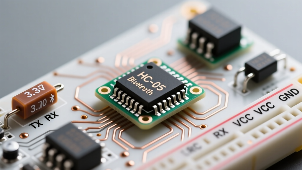
Almost all HC-05 modules sold today are mounted on the ZS-040 breakout board. This board is both a blessing and a curse, primarily due to how it handles voltage regulation. Below is the standard pinout matrix:
| Pin | Function | Hardware Reality & Tolerances |
|---|---|---|
| KEY | AT Mode Trigger | Must be pulled HIGH (3.3V) before power-on to enter command mode. |
| VCC | Power Input | Accepts 3.6V to 6.0V. Onboard AMS1117-3.3 LDO regulates this down. |
| GND | Ground | Common ground required with host MCU. |
| TXD | UART Transmit | Outputs 3.3V logic. Safe to connect directly to 5V Arduino RX. |
| RXD | UART Receive | Strictly 3.3V tolerant. Will degrade or fry if fed 5V logic. |
| STATE | Connection Status | Outputs HIGH when paired, LOW when disconnected. |
The 5V to 3.3V Logic Level Trap
The most common reason hobbyists destroy their HC-05 modules is ignoring the logic level mismatch. While the VCC pin features an onboard AMS1117-3.3 LDO that safely accepts 5V from an Arduino Uno, the RX pin does not have this protection. Feeding a 5V TX signal from an Arduino directly into the HC-05's 3.3V RX pin will slowly degrade the CSR BC417 silicon, leading to dropped packets and eventual bricking.
To interface a 5V microcontroller with the HC-05 safely, you must use a logic level shifter or a simple resistor voltage divider. As detailed in SparkFun's Logic Levels tutorial, a voltage divider using a 1kΩ and 2kΩ resistor will safely step down 5V to 3.33V:
V_out = V_in × (R2 / (R1 + R2))
V_out = 5V × (2000 / (1000 + 2000)) = 3.33V
Entering AT Command Mode: The 38400 Baud Quirk
Configuring the HC-05 as a Master (to connect to another Bluetooth device) or changing its baud rate requires AT Command Mode. Unlike data mode, which defaults to 9600 baud, the ZS-040 breakout board's AT mode defaults to an unusual 38400 baud.
To enter AT mode on the standard ZS-040 board:
- Disconnect power from the HC-05.
- Press and hold the tiny tactile button on the breakout board (or pull the KEY pin HIGH).
- Apply power to the VCC/GND pins while holding the button.
- Release the button. The onboard LED will now blink slowly (once every 2 seconds), indicating AT mode.
For an exhaustive list of firmware-specific commands, Martyn Currey's definitive HC-05 archive remains the gold standard reference for edge-case firmware variations.
Essential AT Commands for Configuration
AT+ROLE=1: Sets the module to Master mode (required for connecting to other HC-05s or BLE peripherals).AT+ROLE=0: Reverts to Slave mode (default).AT+UART=115200,0,0: Changes the data mode baud rate to 115200.AT+PSWD="1234": Changes the pairing PIN code.
The iOS Blind Spot: SPP vs. BLE
A critical factor in tool selection is your target mobile ecosystem. Because the HC-05 relies on the classic Bluetooth SPP profile, it is completely invisible to iOS devices (iPhones and iPads). Apple restricts classic SPP to MFi (Made for iPod/iPhone) certified hardware. If your project requires native communication with an iOS app, you must abandon the HC-05 and opt for a BLE module like the HM-10 or an ESP32.
HC-05 vs. Modern Alternatives: A 2026 Perspective
How does the HC-05 stack up against modern wireless UART bridges? Here is a practical decision matrix for engineers and hobbyists:
| Module | Protocol | iOS Compatible? | Master/Slave? | Best Use Case |
|---|---|---|---|---|
| HC-05 | Classic SPP | No | Both (Configurable) | Legacy robotics, RC cars, Windows/Android telemetry. |
| HC-06 | Classic SPP | No | Slave Only | Simple one-way sensor logging to Android. |
| JDY-31 | Classic SPP | No | Master/Slave | HC-05 alternative with better AT command syntax. |
| ESP32 | Classic + BLE + WiFi | Yes (via BLE) | N/A (Full MCU) | Modern IoT, iOS apps, high-speed data logging. |
For pure simplicity where no coding of a secondary microcontroller is desired, the HC-05 wins. If you need WiFi or iOS support, the ESP32 is the undisputed king, though it requires writing firmware rather than just passing raw UART strings.
Field Notes: Common Failure Modes & Troubleshooting
Based on extensive field testing, here are the most common failure modes associated with the HC-05 and how to resolve them:
- Pairing Drops Under Load: The CSR BC417 chip draws spikes of current (up to 50mA) during transmission. If powered by the weak 3.3V rail of an Arduino clone, the voltage will sag, causing the module to reboot and drop the Bluetooth connection. Always power the HC-05 VCC pin from a dedicated 5V rail or a separate LiPo battery.
- Bricking via AT Mode: Sending standard 9600-baud data while the module is in 38400-baud AT mode will result in garbage characters and occasionally lock up the firmware. Always ensure your Serial Monitor is set to 38400 baud and configured to send 'Both NL & CR' when issuing AT commands.
- RF Interference: The PCB trace antenna on the ZS-040 is highly susceptible to detuning if placed inside a metal enclosure or directly adjacent to a 2.4GHz WiFi router. Maintain at least a 2-inch clearance from other RF sources.
Final Verdict & Project Recommendations
The HC-05 remains an unparalleled tool for quick, code-free wireless UART bridges between Android devices, PCs, and 8-bit microcontrollers. However, its lack of BLE support and 3.3V logic vulnerabilities require careful hardware design.
If you are building a heavy-duty rover, a wireless OBD2 scanner for an Android head unit, or a retro-computing serial bridge, the HC-05 is highly recommended. For detailed datasheets and schematic footprints, refer to the Components101 HC-05 datasheet. Just remember to respect the 3.3V logic limit, and the HC-05 will serve your projects reliably for years to come.