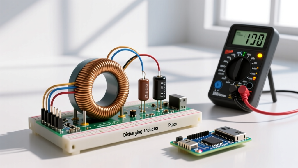

The discharging inductor equation calculates the exponential decay of current in an RL (resistor-inductor) circuit after the DC power source is removed and the inductor dissipates its stored magnetic energy through a resistive path. The direct answer for the current at any given time t is i(t) = I0 · e-(R/L)t. This formula is foundational for designing snubber networks, predicting relay drop-out times, and sizing freewheeling diodes in power electronics.
The Core Discharging Inductor Equation & Symbol Definitions
When a charged inductor is disconnected from its source and shorted through a resistor, the collapsing magnetic field induces a voltage that keeps current flowing in the same direction, but at a decaying rate. The governing time-domain equation is:
i(t) = I0 · e-(R/L)t or i(t) = I0 · e-t/τ
Below is the complete specification table defining every variable, its SI unit, and practical bench notes.
| Symbol | Parameter | SI Unit | Practical Bench Notes |
|---|---|---|---|
| i(t) | Instantaneous current at time t | Amperes (A) | The value you measure with a current probe or calculate for a specific microsecond. |
| I0 | Initial current at t = 0 | Amperes (A) | Calculated via Ohm's Law (V/R) just before the switch opens. |
| e | Euler's number | Dimensionless | Mathematical constant ≈ 2.71828. Use the ex button on your scientific calculator. |
| R | Total discharge resistance | Ohms (Ω) | Includes the external resistor PLUS the inductor's internal DCR (DC Resistance). |
| L | Inductance | Henries (H) | Assumes a linear core. Ferrite/iron powder cores will vary with current levels. |
| t | Time elapsed since discharge began | Seconds (s) | Must be in base seconds to match the Henry/Ohm ratio. |
| τ | Time constant (L/R) | Seconds (s) | The time it takes for current to decay to 36.8% of I0. See Georgia State University HyperPhysics for deeper RC/RL time constant theory. |
Rearranged Forms: Solving for Time, Resistance, and Inductance
On the bench, you rarely just solve for i(t). Usually, you know your target decay time and need to select a bleeder resistor, or you have a fixed inductor and need to find out how long the flyback current will persist. Here are the algebraic rearrangements of the discharging inductor equation:
- Solving for Time (t):
t = -(L / R) · ln(i(t) / I0) - Solving for Resistance (R):
R = -(L / t) · ln(i(t) / I0) - Solving for Inductance (L):
L = -(R · t) / ln(i(t) / I0) - Solving for Initial Current (I0):
I0 = i(t) / e-(R/L)t
Note: 'ln' represents the natural logarithm (base e). Ensure your calculator is not set to base-10 log.
Worked Examples with Strict Unit Tracking
The most common reason engineers and hobbyists get wrong answers from this formula is unit mismanagement. The exponent -(R/L)t must be strictly dimensionless. Since R/L yields units of s-1, time t must be in base seconds. Below are two step-by-step bench scenarios.
Example 1: Calculating Relay Coil Drop-Out Current
Scenario: A 12V DC automotive relay has a coil inductance of 150 mH and a total DC resistance (including the coil wire) of 60 Ω. The relay is driven by a 12V source. When the transistor switch opens, the coil discharges through an internal 120 Ω bleeder resistor (total discharge R = 60 Ω + 120 Ω = 180 Ω). What is the current 2 milliseconds after the switch opens?
- Find Initial Current (I0): Before the switch opens, the inductor is fully charged. I0 = V / Rcoil = 12V / 60Ω = 0.2 A (200 mA).
- Convert Units to Base SI:
- L = 150 mH = 0.15 H
- t = 2 ms = 0.002 s
- R = 180 Ω (already in base units)
- Calculate the Exponent: -(R/L) · t = -(180 / 0.15) · 0.002 = -1200 · 0.002 = -2.4
- Apply the Formula: i(0.002) = 0.2 · e-2.4
- Compute Final Value: e-2.4 ≈ 0.0907. Therefore, i = 0.2 · 0.0907 = 0.0181 A (18.1 mA).
Bench Takeaway: At 2 ms, the current has dropped to roughly 9% of its initial value. If the relay requires 20 mA to stay pulled in, it will drop out just before the 2 ms mark.
Example 2: Sizing a Snubber Resistor for a Target Decay Time
Scenario: You are designing a snubber network for a large 2.5 H smoothing choke in a tube amplifier power supply. The choke has an internal DCR of 100 Ω. The initial current is 0.5 A. You need the current to decay to a safe 10 mA (0.01 A) within 0.5 seconds to protect the rectifier tube. What external bleeder resistor must you place in parallel with the choke?
- Identify Knowns: L = 2.5 H, t = 0.5 s, I0 = 0.5 A, i(t) = 0.01 A.
- Rearrange for Total Resistance (Rtotal):
Rtotal = -(L / t) · ln(i(t) / I0) - Calculate the Natural Log: ln(0.01 / 0.5) = ln(0.02) ≈ -3.912
- Solve for Rtotal: Rtotal = -(2.5 / 0.5) · (-3.912) = -5 · -3.912 = 19.56 Ω
- Determine External Resistor: Wait, the total required resistance is 19.56 Ω, but the choke's internal DCR is already 100 Ω. Because 19.56 Ω is less than the internal DCR, no external series resistor can achieve this. You must use a parallel bleeder resistor.
- Calculate Parallel Resistor (Rp): 1/Rtotal = 1/RDCR + 1/Rp
1/19.56 = 1/100 + 1/Rp
0.0511 = 0.01 + 1/Rp
1/Rp = 0.0411 → Rp ≈ 24.3 Ω
Bench Takeaway: You need a 24 Ω (or standard 25 Ω) high-wattage bleeder resistor in parallel with the choke to meet the 0.5s safety deadline. For more on practical RL snubber design, refer to the Electronics Tutorials RL Circuit Guide.
Boundary Conditions: Assumptions, Unit Traps, and Realistic Magnitudes
The discharging inductor equation is an idealized mathematical model. To use it effectively on the workbench, you must understand where the math diverges from physical reality.
Core Assumptions
- Linear Inductance: The formula assumes L is constant. In reality, inductors with ferromagnetic cores (iron, ferrite) exhibit non-linear inductance. As current drops, the core moves out of saturation, meaning L actually increases during the discharge, causing the tail end of the decay to stretch out longer than the equation predicts.
- Constant Resistance: It assumes R does not change. In high-current pulse circuits, the resistor heats up rapidly, increasing its resistance and altering the time constant dynamically.
- Instantaneous Switching: The math assumes t=0 happens in zero time. Mechanical switches and even MOSFETs have transition times (nanoseconds to microseconds) where the circuit topology is in flux.
Unit Traps That Break the Math
The most fatal error is mixing prefixes. If you use L in milliHenries (mH) and t in milliseconds (ms), the 10-3 factors cancel out, and the math works. However, if you use L in microHenries (μH) and t in milliseconds (ms), your exponent will be off by a factor of 1,000. Rule of thumb: Always convert everything to base SI units (Henries, Ohms, Seconds) before plugging them into the exponent.
Realistic Answer Magnitudes
What does a 'correct' answer look like? In power electronics (like a buck converter operating at 500 kHz), the inductor discharge time is measured in microseconds or nanoseconds. In audio crossover networks or heavy relay controls, it's measured in milliseconds. In high-voltage DC transmission or massive superconducting magnets, discharge times can be measured in minutes or hours. If your calculation for a small PCB inductor yields a decay time of 4 seconds, you have likely forgotten to convert μH to H.
Frequently Asked Questions
How does the discharging inductor equation change with a flyback diode?
When you place a standard freewheeling diode (like a 1N4007) across an inductor, the discharge path is no longer a simple linear resistor. The diode introduces a relatively constant forward voltage drop (Vf, typically 0.7V for silicon). The differential equation becomes L(di/dt) + iR + Vf = 0. This results in a decay curve that is slightly more linear at the end rather than purely exponential, and the current will forcefully snap to zero when the induced voltage can no longer overcome the diode's Vf. For faster decay, engineers use a Zener diode in series with the flyback diode to increase the discharge voltage, intentionally shrinking the time constant.
Why does my calculated inductor discharge time differ from my oscilloscope reading?
If your scope shows ringing (oscillations) instead of a smooth exponential decay, you are no longer looking at a pure RL circuit; you are looking at an RLC circuit. Every physical inductor has parasitic winding capacitance, and your oscilloscope probe adds another 10-15 pF of capacitance. When the switch opens, the inductor's stored energy resonates with this parasitic capacitance. Additionally, core hysteresis and eddy current losses dissipate energy as heat, acting as a hidden parallel resistance that speeds up the decay slightly compared to the ideal DCR-only calculation.
What happens to the discharging inductor equation in an AC circuit?
The time-domain exponential decay equation applies strictly to DC transients (switching events). In a steady-state AC circuit, the inductor is continuously 'charging' and 'discharging' every half-cycle. We abandon the time-domain exponential formula and instead use the phasor domain (frequency domain), applying complex impedance (Z = R + jωL) and Ohm's law for AC (V = I · Z). The concept of a distinct 'discharge phase' only reappears in AC if you suddenly open a switch and interrupt the AC waveform, creating a DC-offset transient decay superimposed on the AC signal.