
The Non-Contact Advantage: Why Go Capacitive?
When designing fluid management systems, aquariums, or automated hydroponics, measuring liquid volume without contaminating the fluid is a primary engineering challenge. Traditional float switches suffer from mechanical wear, calcification, and biofilm buildup. Ultrasonic sensors struggle with foam, condensation, and narrow tanks. This is where the capacitive liquid level sensor dominates. By measuring changes in capacitance through a non-metallic container wall, these sensors provide reliable, non-contact liquid detection. Whether you are building an ESP32-based smart water dispenser or spec'ing out an industrial chemical dosing rig, choosing the right capacitive sensor requires a deep understanding of dielectric physics, signal architecture, and environmental tolerances.
The Physics: Dielectric Constants and Penetration
Capacitive sensors do not 'see' water; they detect changes in the dielectric constant of the material between their sensing electrode and the ground reference. Air has a dielectric constant of roughly 1.0, while pure water sits at approximately 80.0. When a liquid approaches the sensor's electric field, the capacitance spikes. The sensor's internal oscillator detects this shift and triggers a state change.
However, the container wall acts as a parasitic dielectric layer. Polypropylene and ABS plastics typically have dielectric constants between 2.0 and 3.0. If your container wall is too thick, the electric field cannot penetrate it effectively, or the sensor becomes overly sensitive to the wall itself, rendering it useless for detecting the liquid inside. Understanding this boundary condition is the first step in your buying decision.
Decoding the Specs: 4 Dealbreakers Before You Buy
1. Penetration Depth and Wall Thickness
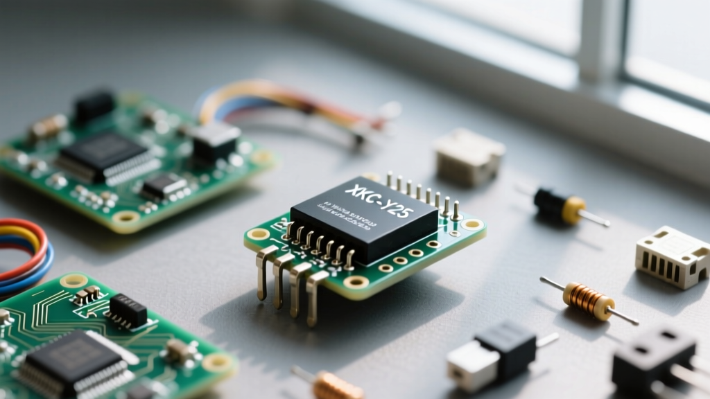
Every capacitive sensor has a maximum penetration depth. For DIY modules like the ubiquitous XKC-Y25 series, this is typically rated between 1mm and 15mm. Industrial probes from manufacturers like IFM or Gems Sensors can often penetrate up to 25mm of glass or PTFE. Pro-Tip: Always buy a sensor rated for a wall thickness at least 20% greater than your actual tank wall to account for manufacturing variances and external condensation layers.
2. Output Signal Architecture
Your microcontroller's GPIO capabilities dictate which sensor you should buy. There are three primary output types in the current market:
- Digital High/Low (NPN/PNP): Best for simple high-water alarms or pump triggers. NPN pulls the signal to ground, while PNP outputs the supply voltage.
- Analog Voltage (e.g., 0-5V): Provides continuous level tracking, but requires careful ADC calibration and is highly dependent on tank geometry.
- Industrial Current Loop (4-20mA): Used in PLC environments to prevent voltage drop over long cable runs. Requires a precision shunt resistor to interface with standard microcontrollers.
3. The Condensation Problem
Water droplets clinging to the inside or outside of the tank wall will trigger false positives. High-end industrial sensors feature 'ignoring algorithms' that differentiate between a thin film of condensation (low capacitance change) and a bulk liquid mass (high capacitance change). If you are buying a cheap DIY module, you must physically mount the sensor slightly above the absolute lowest drain point to avoid pooling water triggers.
Market Breakdown: DIY Modules vs. Industrial Probes
To help you navigate the market, we have categorized the most prominent capacitive liquid level sensors available in 2026. Below is a technical comparison of the most widely used models across the maker and industrial spectrums.
| Model / Series | Target Audience | Output Type | Max Wall Thickness | Avg. Price (USD) |
|---|---|---|---|---|
| XKC-Y25-NP (Generic) | Arduino / DIY Makers | Digital NPN (Open Collector) | 15mm (Non-metallic) | $3.50 - $5.00 |
| XKC-Y25-V | Continuous Level Tracking | Analog Voltage (0-5V) | 15mm (Non-metallic) | $4.00 - $6.50 |
| DFRobot SEN0205 | Education / Prototyping | Digital (Gravity I/O) | 13mm (Plastic/Glass) | $12.00 - $15.00 |
| IFM KI5085 | Industrial / PLC Integration | NO/NC Programmable | 25mm (PTFE/Glass) | $110.00 - $145.00 |
Wiring and Microcontroller Integration
Logic Level Shifting and Pull-Up Resistors
A common mistake when integrating the XKC-Y25-NP into 3.3V systems (like the ESP32 or Raspberry Pi Pico) is ignoring the open-collector nature of the output. The NPN transistor inside the sensor pulls the output line LOW when liquid is detected, but it does not actively drive the line HIGH. If your microcontroller's internal pull-up resistors are too weak (often 40kΩ to 50kΩ), the long signal wires will act as antennas, picking up electromagnetic interference (EMI) and causing phantom triggers.
The Fix: Always add an external 4.7kΩ or 10kΩ pull-up resistor tied to your microcontroller's 3.3V rail. Furthermore, keep the signal wire under 24 AWG and as short as physically possible. According to Analog Devices' guidelines on capacitive sensor design, parasitic capacitance from long, unshielded wires can easily exceed the capacitance change caused by the liquid itself, leading to permanent false-high states.
Real-World Failure Modes and Calibration Fixes
Even the best sensors fail if deployed blindly. Here are the most common failure modes reported by systems integrators and how to engineer around them:
Field Note: 'I spent three days debugging a hydroponics nutrient tank that kept triggering the overflow alarm. The culprit wasn't the sensor's logic; it was the 120V AC water pump power cable zip-tied directly next to the sensor's signal wire. The AC field induced enough noise to trip the sensor's internal comparator.' - Systems Engineer, Automated Ag-Tech.
1. The Sensitivity Potentiometer Trap
Many generic capacitive modules feature a small trimmer potentiometer on the back for adjusting sensitivity. While tempting to tweak, turning this pot to maximum sensitivity will cause the sensor to trigger from a human hand approaching within 3 inches of the tank. For stable operation, set the potentiometer so that the sensor only triggers when the liquid is within 2mm of the tank wall, and then secure the screw with a drop of non-conductive nail polish or conformal coating to prevent vibration-induced drift.
2. Analog Non-Linearity in Irregular Tanks
If you purchase an analog voltage sensor (like the XKC-Y25-V) to measure exact volume in liters, be aware that the output is inherently non-linear. The electric field spreads out in a teardrop shape. In a cylindrical tank, the capacitance change per centimeter of liquid height will differ from the bottom of the tank to the top. You must map the sensor's ADC values against known physical volumes using a piecewise linear interpolation array in your firmware, rather than assuming a direct 1:1 linear correlation.
Final Decision Framework
Selecting the right capacitive liquid level sensor comes down to your specific operational constraints. If you are building a simple low-water cutoff for a 3D printer resin vat or an automated pet waterer, the XKC-Y25-NP paired with a 10kΩ pull-up resistor and an ESP32 is unbeatable for the price. Its digital output removes the need for complex ADC calibration, and its 15mm penetration depth handles standard acrylic and PETG containers effortlessly.
However, if your application involves aggressive solvents, high-pressure steam, or requires continuous volumetric tracking in a commercial environment, skip the hobbyist modules. Invest in an IP67-rated industrial probe like the IFM KI series. While the upfront cost is significantly higher, the integrated condensation rejection algorithms and robust PTFE sensing faces will save you hundreds of hours in firmware debouncing and maintenance downtime. For further integration specifics, reviewing DFRobot's SEN0205 documentation provides excellent baseline code structures for handling digital state debouncing in Arduino environments.