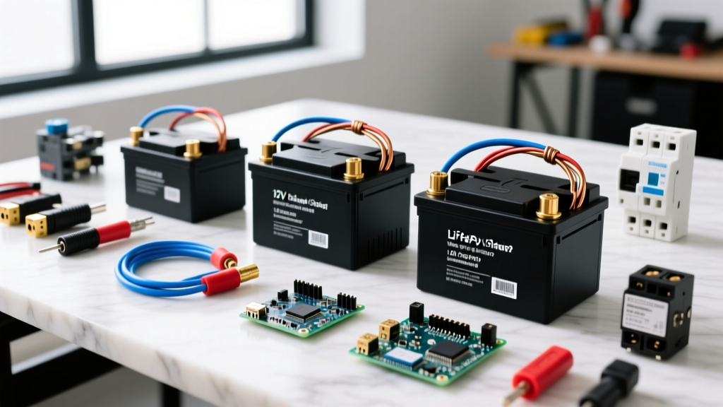
When engineering an off-grid or backup power system, the schema inverter blueprint is the critical bridge between raw DC storage and usable AC power. A well-designed schema dictates everything from wire gauge and busbar topology to the exact charge algorithms required to keep your cells alive. For a standard residential backup or off-grid cabin running a 5kW continuous load, the direct answer is to use a 48V DC architecture paired with a 5000W low-frequency hybrid inverter and a minimum of 10kWh of LiFePO4 storage.
This guide breaks down the exact system block flow, the non-negotiable sizing math, and the wiring specifications required to build a reliable 48V schema inverter layout without melting your lugs or tripping your BMS.
The Core System Block: Source to Load in Your Schema Inverter
A complete schema inverter design follows a strict unidirectional block flow from generation to consumption. Understanding this sequence is vital for placing overcurrent protection and disconnects correctly.
- Source (Solar/Grid): PV strings feed into an MPPT charge controller, while the utility grid feeds into the inverter's AC-In port.
- DC Bus & Storage: The MPPT outputs regulated DC to a common busbar, which ties directly to the battery bank. This is where the heavy 2/0 AWG or 4/0 AWG copper lives.
- Inversion Stage: The inverter draws DC from the bus, converts it to a pure sine wave AC output, and manages AC-In pass-through via an internal automatic transfer switch (ATS).
- Load (AC Panel): The inverter's AC-Out feeds a dedicated critical loads subpanel.
Series vs. Parallel: Consequences for Voltage and Amp-Hours
How you wire your battery modules fundamentally changes your system's operating point. The physical energy (Watt-hours) remains the same, but the electrical characteristics shift drastically:
- Series Wiring: Voltages add; Amp-hours (Ah) remain constant. Wiring four 12V 100Ah batteries in series yields 48V at 100Ah (4,800Wh). This is the preferred method for 5kW+ schemas because higher voltage means lower current, allowing you to use smaller, cheaper wire and reducing I²R heat losses.
- Parallel Wiring: Amp-hours add; Voltage remains constant. Wiring the same four batteries in parallel yields 12V at 400Ah (4,800Wh). Pulling 5000W from a 12V bank requires over 416 amps of continuous current, which demands massive 4/0 AWG cables and multiple parallel busbars. Avoid 12V for schemas exceeding 2000W.
Battery Bank Sizing: Peukert, C-Rates, and DoD Math
Sizing the DC storage for your schema inverter requires moving past simple Watt-hour addition. We must account for inverter efficiency, Depth of Discharge (DoD) limits, and discharge rates.
The Scenario: You need to run a 3,000W continuous load (refrigerator, well pump, lights, router) for 4 hours during a grid outage.
- Base Energy: 3,000W × 4 hours = 12,000Wh.
- Inverter Efficiency Factor: High-frequency and low-frequency inverters operate at roughly 93% efficiency under load. You must divide by 0.93 (or multiply by 1.075) to find the DC draw. 12,000Wh × 1.075 = 12,900Wh required from the battery.
- Depth of Discharge (DoD): To maximize cycle life, LiFePO4 batteries should not be discharged below 20% State of Charge (an 80% usable DoD). 12,900Wh / 0.80 = 16,125Wh total nameplate capacity required.
- Amp-Hour Conversion: A 16S LiFePO4 battery has a nominal voltage of 51.2V. 16,125Wh / 51.2V = 314.9Ah. You need a minimum 48V 350Ah battery bank.
Peukert's Law and C-Rate Limits
Peukert’s Law states that a battery's effective capacity decreases as the rate of discharge increases. For lead-acid (AGM/Gel), the Peukert exponent is around 1.3, meaning heavy loads drastically shrink your usable Ah. LiFePO4 has an exponent near 1.05, making Peukert losses negligible.
However, lithium cells are strictly bound by C-rate limits (charge/discharge limits). Most server-rack LiFePO4 batteries (like the EG4 or SOK 48V 100Ah models) feature a 100A BMS, but their safe continuous discharge limit is 0.5C (50A).
- Discharge Limit: 50A × 51.2V = 2,560W max continuous per battery. To pull our 3,000W load without tripping the BMS, a single 100Ah battery is insufficient. You must parallel two 48V 100Ah batteries (yielding 100A continuous / 5,120W capacity) to safely meet the C-rate requirement.
- Charge Limit: Standard LiFePO4 accepts a 0.5C charge rate (50A max). If your MPPT controller pushes 80A, you must either limit the charge current in the MPPT software or add more parallel batteries to absorb the current safely.
Inverter and Charger Sizing for Real-World Loads
The inverter is the engine of your schema. Sizing it requires looking at both continuous thermal limits and magnetic surge limits for inductive loads.
| Specification | Requirement | Target Hardware Metric |
|---|---|---|
| Continuous AC Load | 3,000W | Minimum 4,000W continuous rating |
| Surge Load (Well Pump/Compressor) | 9,000W for 3 seconds | Minimum 10,000W (2x continuous) surge rating |
| DC Input Voltage | 48V Nominal (40V-58V range) | 48V DC bus architecture |
| AC Charger (Grid Generator Input) | Replenish 200Ah bank in 4 hours | Minimum 50A internal AC charger |
For a 3,000W continuous load with heavy motor surges, a 5000VA (4800W continuous) hybrid inverter/charger is the sweet spot. Units like the Victron Energy MultiPlus-II 48/5000 or the EG4 6000XP provide the necessary low-frequency toroidal transformers or high-frequency DSP topologies to handle the locked-rotor amperage (LRA) of a 1.5HP well pump without dropping the AC voltage below the 114V brownout threshold.
Charger Sizing: If your schema includes a grid-tie or generator backup, the internal AC charger must be sized to recharge the bank while simultaneously passing power to the loads. A 5000W inverter with a 100A built-in charger can pull roughly 12,000W from the grid (5000W for loads + 5000W for battery charging + losses). Ensure your upstream AC breaker and generator can handle this combined pass-through draw.
Decision Tree: Picking Your Exact Inverter and Battery Combo
Stop guessing. Use this decision matrix to lock in your exact part numbers based on your budget and reliability requirements.
| If Your Scenario Is... | Then Choose This Inverter | And Pair With This Battery |
|---|---|---|
| Budget Off-Grid / DIY Backup (Under $3,000 total, willing to use proprietary BMS comms, high value-per-watt needed) |
EG4 6000XP 48V Inverter (6000W continuous, 12000W surge) |
2x EG4 48V100AH Smart Server Rack Batteries (10.2kWh total, 0.5C discharge) |
| Critical Medical / Marine / High-End ($4,500+ budget, requires Victron VRM telemetry, parallel stacking, and 10-year proven reliability) |
Victron MultiPlus-II 48/5000 (4800W continuous, 9000W surge) |
2x SOK 48V 100Ah LiFePO4 or 1x Discover AES 48V (BMS fully integrates with Victron CAN bus) |
| Whole-Home 200A Service Split-Phase (Needs 240V split-phase output without external autotransformers) |
2x Sol-Ark 15k stacked OR 1x EG4 18kPV (High-voltage DC bus, integrated AC coupling) |
EG4 FlexBoss 14.3kWh High Voltage Battery (Requires HV architecture, not 48V) |
Wiring the Schema: Torque, Lugs, and Safety Callouts
A perfect schematic fails if the physical terminations are flawed. DC arcs and high-resistance joints are the primary causes of inverter fires. Follow these physical wiring rules strictly, adhering to NFPA 70 (National Electrical Code) guidelines for DC power systems.
Wire Gauge and Overcurrent Protection
For a 5000W 48V inverter, your peak continuous DC draw is roughly 115A (accounting for low-voltage cutoff at 44V and 93% efficiency).
- Wire Size: Use 2/0 AWG stranded copper wire (rated 75°C or 90°C). 2/0 AWG has an ampacity of 175A in the 75°C column, providing a massive safety margin and minimizing voltage drop to under 1% over a 5-foot run.
- Fusing: Install a 150A Class T fuse on the positive battery cable, within 7 inches of the battery busbar. Class T fuses have a 20,000A interrupt capacity (AIC), which is mandatory for lithium banks capable of dumping thousands of amps during a dead short. Never use standard ANL fuses for main lithium bank protection; their AIC is too low.
Lug Crimping and Torque Specs
Do not rely on "hand tight." Inverter manufacturers specify exact torque values because copper expands and contracts under thermal load. A loose M8 nut on a Victron or EG4 DC terminal will increase contact resistance. That resistance generates heat, which melts the terminal block and causes an arc flash.
- Strip exactly 7/8" of insulation from the 2/0 AWG wire.
- Use a closed-end copper lug with a 5/16" or M8 stud hole.
- Crimp using a hydraulic hex-crimper (not a hammer crimper) to ensure a gas-tight cold weld.
- Apply a thin layer of di-electric grease or NO-OX-ID A-Special to the busbar contact face to prevent galvanic corrosion.
- Torque the M8 terminal nut to 12 to 15 Nm (8.8 to 11 lb-ft) using a calibrated 1/4" drive torque wrench.
By locking in your 48V architecture, respecting the 0.5C lithium discharge limits, and terminating your 2/0 AWG cables to exact torque specs, your schema inverter will deliver years of uninterrupted, safe power. Stop planning and start wiring the EG4 6000XP ecosystem today.