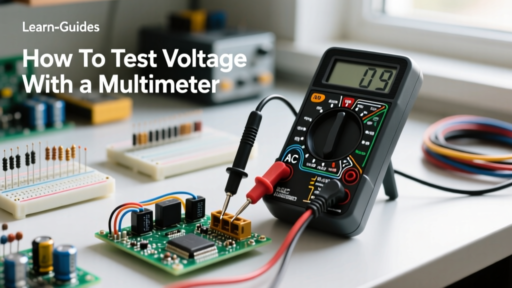

Whether you are troubleshooting a dead wall outlet, diagnosing a parasitic drain on a car battery, or debugging a custom PCB, understanding how to test for voltage with a multimeter is the most fundamental skill in electrical diagnostics. Voltage, or electrical potential difference, is the invisible pressure that pushes electrons through a conductor. Without verifying voltage, you are essentially working blind. This comprehensive guide moves beyond the basics, exploring the physics of potential difference, the critical differences between AC and DC measurements, and advanced diagnostic techniques like Low Impedance (LoZ) testing to eliminate ghost voltages.
The Physics of Potential Difference: What Are We Actually Measuring?
Before touching the probes to a live circuit, it is crucial to understand what the multimeter is actually calculating. Voltage is measured in Volts (V) and represents the work needed to move a unit of charge between two points. When you learn how to test for voltage with a multimeter, you are not measuring the flow of current; you are measuring the pressure available to cause flow.
Multimeters measure this by utilizing an internal analog-to-digital converter (ADC) with a very high input impedance, typically around 10 Megohms. This high impedance ensures that the meter draws virtually zero current from the circuit under test, preventing the act of measurement from altering the circuit's behavior or collapsing the voltage entirely.
Decoding the Multimeter Dial: V⎓ vs V~
The most common point of failure for beginners is selecting the wrong voltage mode. The multimeter dial features two distinct voltage settings, and confusing them can lead to inaccurate readings or, in severe cases, damage to the meter.
- V⎓ (or VDC): The solid line with dashed lines beneath it represents Direct Current. This mode measures steady, unidirectional voltage. Use this for batteries, automotive systems, solar panels, and the logic rails on a PCB (e.g., 3.3V or 5V).
- V~ (or VAC): The wavy line represents Alternating Current. This mode measures voltage that periodically reverses direction. Use this for residential mains power (120V/240V), HVAC systems, and AC transformers. In AC mode, the multimeter calculates the Root Mean Square (RMS) value, which represents the equivalent DC voltage that would deliver the same power to a resistive load.
Tool Selection: True RMS, LoZ, and CAT Ratings
Not all multimeters are created equal. When working with AC voltage, particularly in environments with variable frequency drives or non-linear loads (like LED drivers and computer power supplies), a standard average-responding multimeter will give you wildly inaccurate readings. You need a True RMS meter. Furthermore, safety is paramount. According to the Fluke Multimeter Safety Guide, you must ensure your meter and probes carry the correct Category (CAT) rating for your environment.
| Feature | Standard / Budget Meter | Professional / Industrial Meter | Why It Matters |
|---|---|---|---|
| AC Measurement | Average-Responding | True RMS | True RMS accurately measures distorted sine waves common in modern electronics. |
| Safety Rating | CAT II 600V (or unrated) | CAT III 600V / CAT IV 600V | CAT III/IV meters have internal blast shields and arc-gap protection to prevent explosions during transient spikes. |
| Input Impedance | Fixed 10 MΩ | Switchable 10 MΩ / LoZ (3 kΩ) | LoZ mode bleeds off capacitive coupling to prevent false 'ghost' voltage readings. |
| Example Models | Klein Tools MM400 | Fluke 117 / Fluke 87V | Professional models offer higher durability, speed, and safety certifications. |
Exact Procedure: How to Test for Voltage With a Multimeter on DC Circuits
Testing DC voltage is straightforward, but probe placement and range selection dictate your accuracy. Follow this precise sequence:
- Probe Insertion: Plug the black probe into the COM (Common) jack. Plug the red probe into the V/Ω (Volts/Ohms) jack. Never leave the red probe in the Amps (A) or Milliamps (mA) jack when testing voltage; this creates a dead short and will blow the internal fuse or destroy the meter.
- Dial Selection: Turn the dial to V⎓. If your meter is not auto-ranging, select a DC voltage range higher than your expected reading (e.g., choose the 20V setting when testing a 12V car battery).
- Connection: Touch the red probe to the positive (+) terminal or the more positive node in the circuit. Touch the black probe to the negative (-) terminal or ground.
- Reading Interpretation: If you see a negative sign (e.g., -12.6V), it simply means your probes are reversed relative to the polarity of the circuit. The absolute voltage value is still correct.
Exact Procedure: Testing AC Mains and High-Voltage Sources
Testing AC voltage introduces severe safety hazards. As outlined by OSHA Electrical Safety Standards, arc flashes and lethal shocks are real risks when probing live mains. Use the 'One-Hand Rule' whenever possible, keeping your non-dominant hand in your pocket to prevent current from crossing your chest in the event of an accidental shock.
- Inspect Probes: Check for any cracks, exposed wire, or worn CAT ratings on the probe insulation. Discard damaged probes immediately.
- Dial Selection: Turn the dial to V~. For North American residential outlets, select a range above 120V (usually the 600V setting on manual meters).
- Connection: For a standard duplex receptacle, insert one probe into the shorter slot (Hot) and the other into the longer slot (Neutral). You should read between 110V and 125V.
- Ground Verification: Move the probe from the Neutral slot to the round Ground hole. You should read the same voltage. If you read 0V between Hot and Ground, you have an open ground fault, which is a severe safety hazard.
Phantom Voltages and the LoZ Solution
One of the most confusing phenomena you will encounter when learning how to test for voltage with a multimeter is 'ghost' or phantom voltage. This occurs in high-impedance circuits, particularly in long runs of Romex or MC cable where unenergized wires run parallel to energized ones. The capacitance between the wires induces a small AC voltage on the dead wire.
Because a standard digital multimeter has an input impedance of 10 Megohms, it requires almost zero current to register a voltage. Consequently, your meter might display 60V or even 90V on a completely disconnected, dead wire. To solve this, professional meters like the Fluke 117 feature a LoZ (Low Impedance) mode. Engaging LoZ drops the meter's internal resistance to around 3 kilo-ohms. This creates a small load that bleeds off the capacitively coupled phantom voltage, dropping the reading to a true 0V, while still accurately measuring hard-wired, capable voltage sources.
Pro-Tip from the Bench: If your multimeter measures voltage perfectly but reads '0.00' or 'OL' when you try to measure current (Amps), your voltage circuitry is fine. You have simply blown the internal ceramic shunt fuse located on the current measurement pathway. Replace the fuse with the exact same amperage and interrupting capacity (e.g., HRC 11A 1000V) specified by the manufacturer.
Diagnostic Matrix: Unexpected Readings and Fixes
Voltage testing is rarely about just getting a number; it is about interpreting what that number means for the health of the system. Use this diagnostic matrix to troubleshoot common anomalies.
| Scenario | Expected Reading | Actual Reading | Probable Cause & Solution |
|---|---|---|---|
| Automotive 12V Battery (Engine Off) | 12.6V | 10.5V | The battery has a dead cell or is severely sulfated. It requires replacement, not just charging. |
| Standard US Wall Outlet | 120V AC | 108V AC | Excessive voltage drop due to a loose neutral connection at the panel or an overloaded circuit. Check terminations. |
| Li-Ion Cell (18650) | 3.7V Nominal | 2.1V DC | The cell is deeply discharged. Standard chargers will reject it. Requires a specialized 0V recovery function or safe disposal. |
| Thermostat Control Wire (AC) | 24V AC | 27V AC | Normal. HVAC transformers are often unregulated and will output higher voltage when the load (compressor/fan) is not engaged. |
Final Thoughts on Multimeter Mastery
Mastering how to test for voltage with a multimeter is the gateway to advanced electrical diagnostics. By understanding the difference between True RMS and average measurements, respecting CAT safety ratings, and utilizing features like LoZ to defeat ghost voltages, you elevate your troubleshooting from guesswork to precision science. Always verify your meter on a known live source before and after testing a dead circuit to ensure the meter and leads are functioning correctly—a practice known as the Live-Dead-Live test. For more detailed tutorials on measuring current and resistance, consult the SparkFun Multimeter Tutorial to continue building your electronics diagnostic toolkit.